Suspended pile, construction method of suspended pile, and pile side frictional resistance test method

A friction resistance and pile side technology, which is applied to the structural type of suspended piles and the field of side friction resistance testing, can solve problems such as cumulative error and inability to interpret test results, and achieve the effect of small test data error and high success rate of data collection.

Active Publication Date: 2019-04-12
CHINA UNIV OF GEOSCIENCES (BEIJING)
View PDF5 Cites 0 Cited by
  • Summary
  • Abstract
  • Description
  • Claims
  • Application Information

AI Technical Summary

Problems solved by technology

[0004] The method of testing the lateral friction of the pile foundation with the steel strain gauge has the following disadvantages: 1) The strain gauge test method is based on the assumption of homogeneous and linear materials, on which the axial force of the pile is the linear superposition of the steel stress and the concrete stress, Concrete itself is a heterogeneous and non-linear material, and the pile foundation as a steel and concrete composite has stronger heterogeneity; 2) This method is an indirect measurement method, so the test results will be added to the environment (temperature, Humidity, etc.), construction, materials, testing and other aspects of the error, and even unexplainable test results

Method used


Image

  • Suspended pile, construction method of suspended pile, and pile side frictional resistance test method
  • Suspended pile, construction method of suspended pile, and pile side frictional resistance test method
  • Suspended pile, construction method of suspended pile, and pile side frictional resistance test method

Examples


Embodiment Construction

[0038] The present invention will be described in further detail below in conjunction with the embodiments and accompanying drawings. The following embodiments are only descriptive, not restrictive, and cannot limit the protection scope of the present invention.

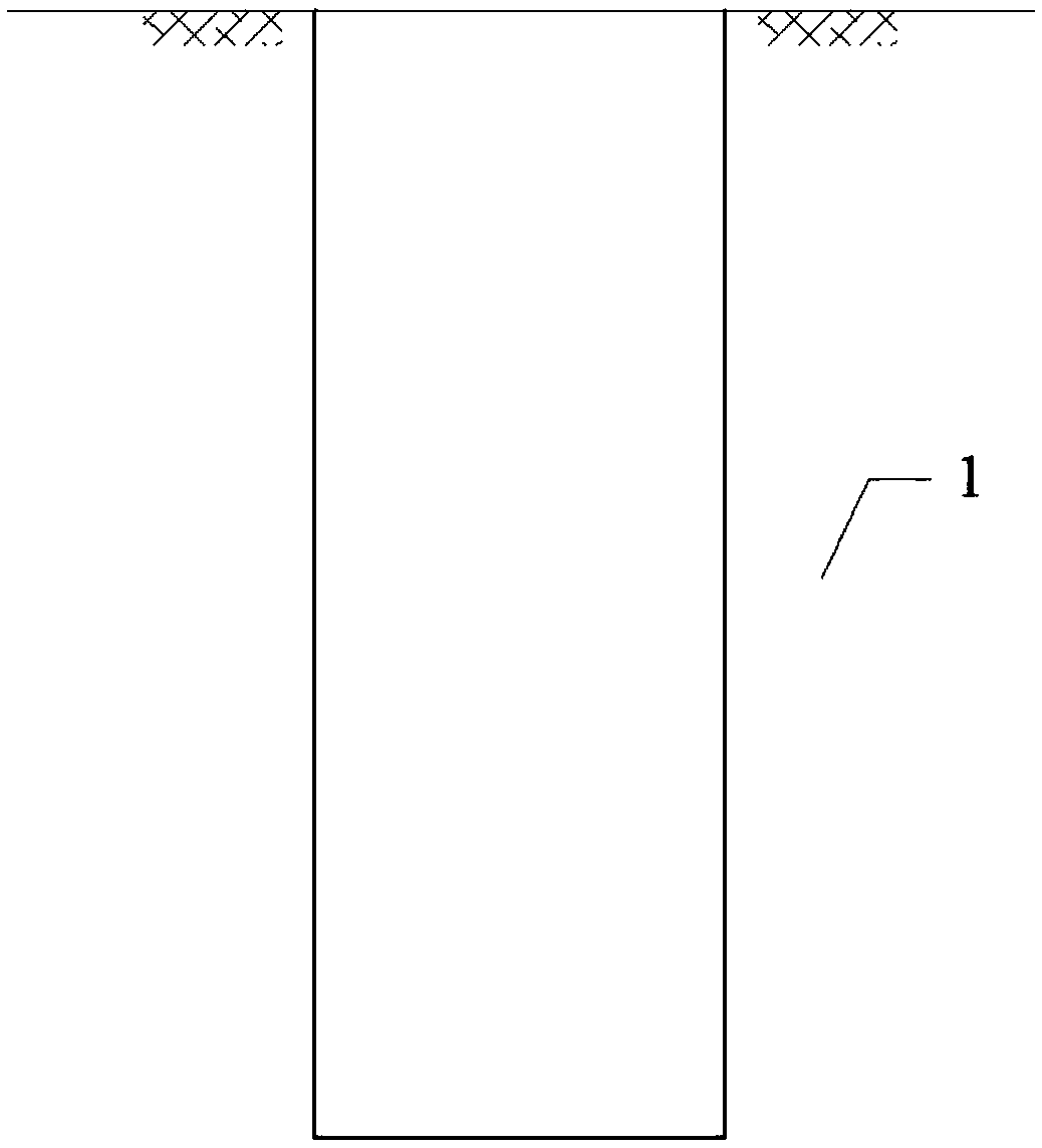
[0039] like figure 1 As shown, a foundation pit is excavated on foundation 1.

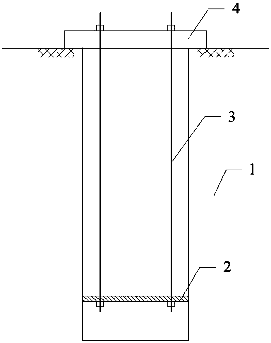
[0040] like figure 2 As shown, the anchor plate 2 is hoisted into the foundation pit through the pull rod 3, and a certain space is reserved between the anchor plate 2 and the bottom of the foundation pit. After the anchor plate 2 is hoisted in place, the upper end of the pull rod 3 is fixed on the cross arm 4 straddling the opening of the foundation pit.

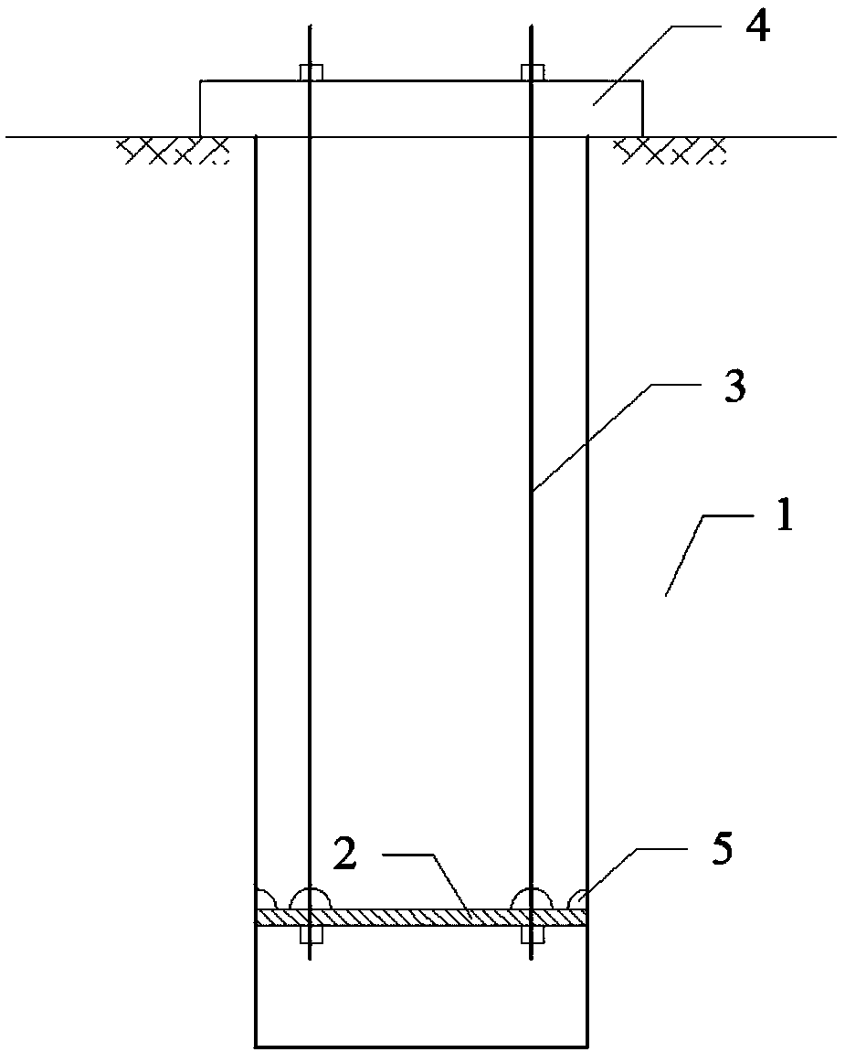
[0041] like image 3 As shown, after the anchor plate 2 is erected, the gap between the anchor plate 2 and the wall of the foundation pit and the assembly gap between the anchor plate 2 and the tie rod 3 are sealed with a sealant 5 .

[0042] like Figure 4 As shown, after the s...


PUM


Abstract

The invention discloses a suspended pile for pile side frictional resistance test, a construction method of the suspended pile, and a pile side frictional resistance test method performed on the basisof the suspended pile. The suspended pile comprises an integrally formed two-section structure including an upper section structure and a lower section structure, wherein the lower section structureis a test section; the upper section structure is a free section; a step surface is formed in the upper end of the test section; a first displacement extending rod and a second displacement extendingrod are pre-buried in the pile body; each of the first displacement extending rod and the second displacement extending rod is a hollow rod; a core rod is inserted in the axial direction of a cavity of the hollow rod; the bottom end of the core rod of the first displacement extending rod passes through the hollow rod to be fixed with the bottom of the test section; the bottom end of the core rod of the second displacement extending rod passes through the hollow rod to be fixed with the bottom of the free section; a displacement sensor is arranged in a way of corresponding to the upper end of each core rod; a jack is arranged at the upper end surface of the free section; and a counterforce beam is put on the jacking end surface of the jack. The suspended pile with the simple structural formhas the advantages that the structure is simple; the test result is accurate; and the construction technical difficulty is small.

Description

technical field [0001] The invention belongs to a pile foundation construction method, and relates to a structure type of a suspended pile and a side friction resistance test method. Background technique [0002] In the prior art, pile foundations are widely used in railways, highways, bridges, buildings, and water conservancy projects in various countries due to their good formation penetration, high vertical and horizontal bearing capacity, and deformation resistance stiffness. Pile is often used as the substructure of buildings (structures) to transfer loads to the deep part of the foundation. This substructure is called pile foundation. [0003] Side friction resistance is the ratio of the bearing capacity of the foundation-pile foundation interface to the area, and is a key parameter in the design of pile foundations. Currently, the commonly used test method is the steel strain gauge test method. In this method, 1) measure the steel bar strain under different levels of...

Claims


Application Information

Patent Timeline
Patent Type & Authority Applications(China)
IPC IPC(8): E02D5/34E02D33/00
CPCE02D5/34E02D33/00
Inventor 乾增珍邓文超张晓东
Owner CHINA UNIV OF GEOSCIENCES (BEIJING)
Why Eureka
Try Eureka