
Centrifugal compressor and design method thereof

A technology of centrifugal compressor and design method, applied in computer-aided design, mechanical equipment, calculation and other directions, can solve the problem that the total pressure ratio cannot be further improved, and achieve the effect of increasing the pressure, increasing the total pressure ratio, and improving the total pressure ratio.

Active Publication Date: 2019-04-12
AECC HUNAN AVIATION POWERPLANT RES INST
View PDF11 Cites 4 Cited by
  • Summary
  • Abstract
  • Description
  • Claims
  • Application Information

AI Technical Summary

Problems solved by technology

[0003] The invention provides a centrifugal compressor and its design method to solve the problem that the existing centrifugal compressor cannot further increase the total pressure ratio

Method used


Image

  • Centrifugal compressor and design method thereof
  • Centrifugal compressor and design method thereof
  • Centrifugal compressor and design method thereof

Examples


Embodiment Construction

[0034] It should be noted that the embodiments in the application and the features in the embodiments can be combined with each other if there is no conflict. Hereinafter, the present invention will be described in detail with reference to the drawings and in conjunction with the embodiments.

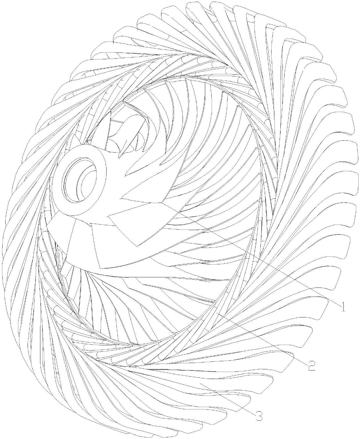
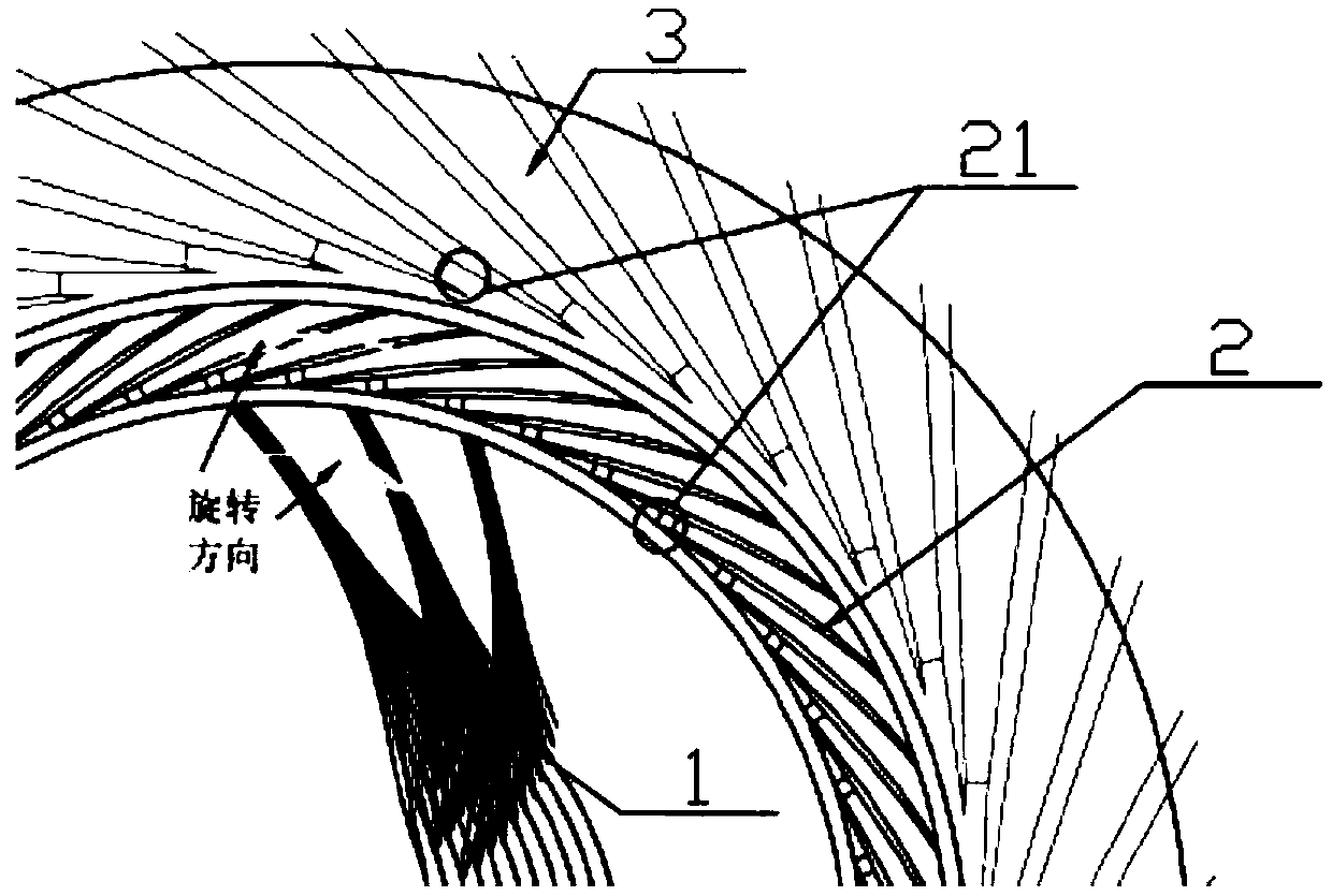
[0035] figure 1 Is one of the schematic diagrams of the centrifugal compressor of the preferred embodiment of the present invention; figure 2 It is the second schematic diagram of the centrifugal compressor of the preferred embodiment of the present invention; image 3 It is the third schematic diagram of the centrifugal compressor of the preferred embodiment of the present invention; Figure 4 It is the fourth schematic diagram of the centrifugal compressor of the preferred embodiment of the present invention; Figure 5 Is a schematic diagram of the forward-swept structure of the preferred embodiment of the present invention; Image 6 It is a schematic diagram of the outlet velocity triang...


PUM

PropertyMeasurementUnit
Corneraaaaaaaaaa
Corneraaaaaaaaaa

Abstract

The invention provides a centrifugal compressor and a design method thereof. The centrifugal compressor comprises a front-row centrifugal impeller, a rear-row centrifugal impeller and an axial diffuser, wherein the front-row centrifugal impeller is used for forming an airflow channel to enable airflow to pass and applying work to the airflow through centrifugal force, the rear-row centrifugal impeller is located at an airflow outlet of the front-row centrifugal impeller and used for forming an airflow channel to enable airflow to pass and applying work to the airflow through centrifugal force,and the axial diffuser is located at an airflow outlet of the rear-row centrifugal impeller and used for speed-reducing diffusion of the airflow and enabling the airflow to be changed to the axial direction from the radial direction. The rotating direction of the rear-row centrifugal impeller is opposite to the rotating direction of the front-row centrifugal impeller, so that the front-row centrifugal impeller provides reversed pre-rotation for the rear-row centrifugal impeller. According to the centrifugal compressor, under the condition that the axial size is basically not changed, the rear-row centrifugal impeller replaces a conventional radial diffuser, the double advantages of centrifugal force and high power capacity of reverse pre-rotation are fully utilized, and the purpose that the overall pressure ratio of the centrifugal compressor is greatly improved under the condition of a compact structure is achieved.

Description

Technical field [0001] The present invention relates to the technical field of centrifugal compressors, in particular to a centrifugal compressor. In addition, the present invention also relates to a method for designing a centrifugal compressor. Background technique [0002] In order to further increase the total pressure ratio, the existing centrifugal compressor can increase the tangent speed of the centrifugal impeller outlet on the one hand, but due to material limitations, the tangent speed cannot be increased indefinitely, and the total pressure ratio has limited potential. In addition, high tangent speeds The structural strength and life span of the centrifugal compressor are unfavorable. On the other hand, a multi-stage centrifugal compressor can be used, but the gas compression flow path has a longer stroke and there are large curvature turns between the flow paths. The flow loss is serious, which is not conducive to the efficiency of the centrifugal compressor, and it...

Claims


Application Information

Patent Timeline
IPC IPC(8): F04D17/12F04D29/28F04D29/44G06F17/50
CPCF04D17/12F04D29/286F04D29/441G06F30/17G06F2111/10G06F2119/06
Inventor 金海良谢建陈璇银越千邹学奇温泉
Owner AECC HUNAN AVIATION POWERPLANT RES INST
Learn More