Automatic disengaging and engaging projectile hoist

An automatic clutch and bomb lifter technology, applied in the direction of ammunition supply, weapon accessories, launchers, etc., can solve the problems of no bomb supply speed, greatly reduced bomb supply resistance, affecting the work of the automaton, etc., to achieve a simple structure, guaranteed The effect of consistency

Inactive Publication Date: 2019-04-12
SICHUAN HUAQING MACHINERY
View PDF5 Cites 2 Cited by
  • Summary
  • Abstract
  • Description
  • Claims
  • Application Information

AI Technical Summary

Problems solved by technology

Therefore, relying on the energy of the automatic machine of the weapon itself often reduces the radio frequency, affects the work of the automatic machine, and affects the stopping position of the weapon due to the high resistance of the bomb supply.
[0003] Therefore, it is necessary to add a device that provides power to the large-caliber rotary tube weapon, that is, the bomb lifter. The bomb lifter on the traditional artillery does not have a feed speed of 3000 rounds per minute and the clutch device cannot meet the large-caliber high-speed rotation. Need for weapons

Method used


Image

  • Automatic disengaging and engaging projectile hoist
  • Automatic disengaging and engaging projectile hoist
  • Automatic disengaging and engaging projectile hoist

Examples


Embodiment Construction

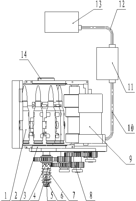
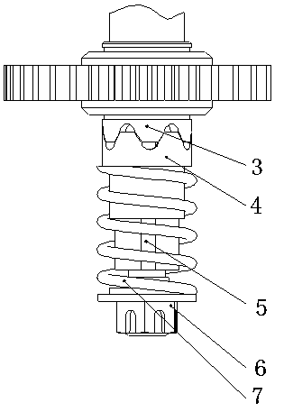
[0022] exist figure 1 Among them, the bomb lifting device 2, the reducer 8, the motor 9, the control cable 10, the controller 11, the power cable 12, and the power supply 13 are connected in sequence. One end of the clutch composed of the clutch fixed block 3, the clutch moving block 4, the transmission shaft 5, the adjusting nut 6 and the adjusting spring 7 is connected with the spring lifting device 2, and the other end is connected with the speed reducer 8. Usually controller 11 outputs a shooting signal and transmits to motor 9 through control cable 10, and motor is transmitted to clutch after speed reducer 8 decelerates, and whether clutch transmits torque according to the resistance size of bullet supply. The torque transmitted by the clutch drives the bullet lifting device 2 to start lifting the bullet, and after the bullet is lifted, under the action of the ratchet mechanism 14, the belt bullet chain 1 is prevented from reversing.

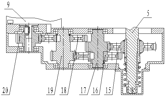
[0023] exist figure 2 In the show...


PUM


Abstract

The invention provides an automatic disengaging and engaging projectile hoist. The automatic disengaging and engaging projectile hoist comprises a driving device, a projectile shifting wheel, a bracket, a disengaging and engaging device movable block and a disengaging and engaging device fixed block; and an automatic disengaging and engaging device is composed of the disengaging and engaging device movable block and the disengaging and engaging device fixed block, one end of the automatic disengaging and engaging device is connected with a projectile hoisting device, and the other end of the automatic disengaging and engaging device is connected with a decelerator. When a projectile supplied by the automatic disengaging and engaging projectile hoist is in a saturated state, the projectilehoisting resistance of the automatic disengaging and engaging projectile hoist is increased, the disengaging and engaging device is separated, and projectile supplying is stopped; and due to continuous shooting, when the projectile is in an unsaturated state, the projectile supplying resistance is decreased, the disengaging and engaging device is closed, and the automatic disengaging and engagingprojectile hoist starts projectile hoisting again. According to the automatic disengaging and engaging projectile hoist, a ratchet wheel is arranged, so that reverse rotation due to the gravity of projectile chains is effectively prevented; and motor starting is earlier than shooting starting, motor stopping is later than shooting stopping, and thus it is ensured that a projectile box guide is always in a saturated state during shooting. The automatic disengaging and engaging projectile hoist provides power for projectile supplying of a large-aperture gatling weapon, consistency of projectileshooting and projectile supplying is ensured, the projectile hoisting speed is larger than or equal to the shooting speed, and thus the high-speed shooting requirement can be met.

Description

technical field [0001] The invention relates to the field of large-caliber high-firing-velocity revolving tube weapons, in particular to the technical field of ammunition feeding devices. Background technique [0002] At present, large-caliber and high-speed revolving tube weapons are developing rapidly. Large-caliber revolving tube weapons are famous for their high rate of fire, high lifespan, and large ammunition capacity. However, there are many technical problems that need to be solved for large-caliber revolving tube weapons. The bullet problem has always been a difficult problem to be solved for large-caliber revolving tube weapons. Nowadays, large-caliber revolving weapons have a large ammunition feeder and a long feeding path. They have to be transmitted to the hard guide through the ammunition box, then to the soft guide, and finally transmitted to the feed port to be supplied to the automatic machine through the dial wheel. Therefore, relying on the energy of the ...

Claims


Application Information

Patent Timeline
Patent Type & Authority Applications(China)
IPC IPC(8): F41F1/08F41A9/30F41A9/51
CPCF41A9/30F41A9/51F41F1/08
Inventor 王朋飞周康平王茂贵杨建军
Owner SICHUAN HUAQING MACHINERY
Why Eureka
Try Eureka