Spherical motor rotor location detection method based on Hall elements

A technology of rotor position detection and Hall element, applied in electrical components, electromechanical devices, electrical devices, etc., can solve the problems of inconvenient system operation, large system volume, increased frictional resistance, etc., and achieve simple hardware structure and solution speed. Fast, high coverage effect

Inactive Publication Date: 2019-04-12
TIANJIN UNIV
View PDF5 Cites 4 Cited by
  • Summary
  • Abstract
  • Description
  • Claims
  • Application Information

AI Technical Summary

Problems solved by technology

The measurement method based on the sliding rail bracket and the rotary encoder requires a special lead structure to couple the rotor direction and the encoder, which increases frictional resistance and brings inconvenience to the system operation
The measurement method based on the photoelectric encoder needs to spray color on the surface of the rotor, and in order to improve the resolution, more photoelectric encoders need to be arranged, which increases the complexity of the system
However, systems based on visual sensors are large in size and difficult to integrate, and the detection speed is restricted by the processing speed of visual graphics.

Method used


Image

  • Spherical motor rotor location detection method based on Hall elements
  • Spherical motor rotor location detection method based on Hall elements
  • Spherical motor rotor location detection method based on Hall elements

Examples


Embodiment Construction

[0031] The present invention provides a design method of a Hall element-based spherical motor rotor position detection system, and verifies its accuracy through a three-axis turntable. The present invention will be described in detail below in conjunction with the accompanying drawings and examples. Concrete implementation steps of the present invention are as follows:

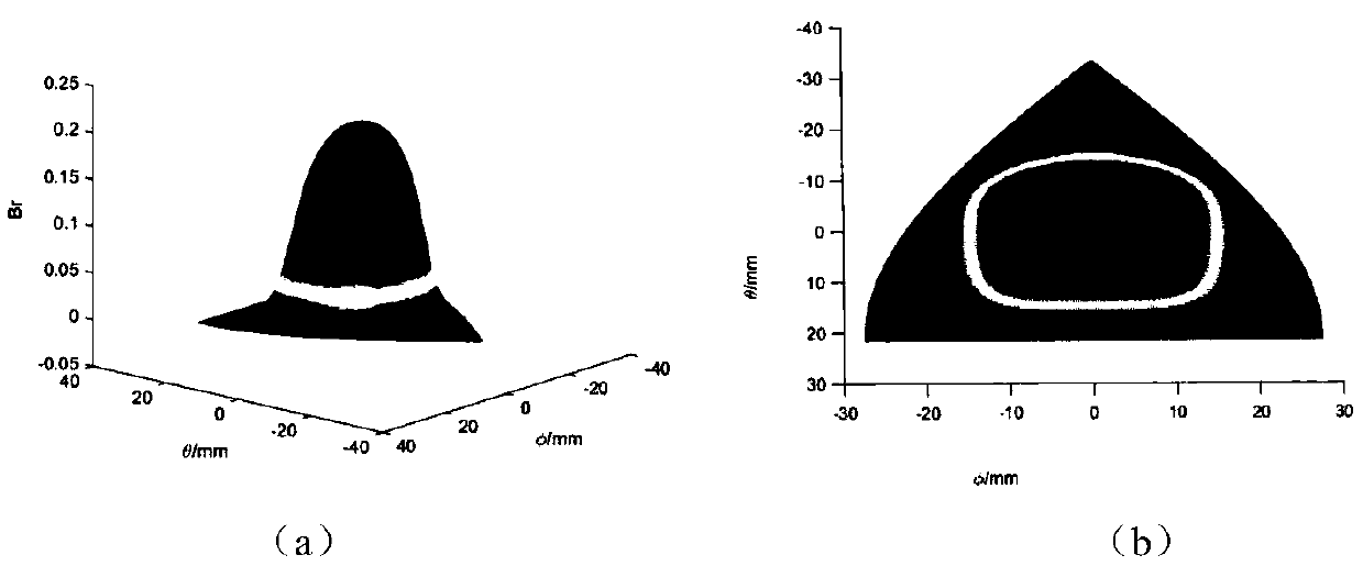
[0032] (1) Establish the surface magnetic field expression of the spherical motor rotor, and then solve the spatial radial magnetic field matrix of the entire rotor spherical surface according to the magnetic field expression.

[0033] The spherical motor rotor model studied in this patent is based on the paper (Li B, Li Z, Li G. Magnetic Field Model for Permanent Magnet Spherical Motor with Double Polyhedron Structure [J]. IEEE Transactions on Magnetics, 2017, PP(99): 1-1 .) The spherical motor structure proposed in , which contains 8 permanent magnet poles, and its N and S stages are alternately distributed ...


PUM


Abstract

The invention relates to a spherical motor rotor location detection method based on Hall elements. The method comprises the following steps: solving out a space radial magnetic field matrix of the whole rotor spherical surface; based on the features of the rotor magnetic field, fitting magnetic field contour lines surrounding a rotor magnetic pole by using ellipse; adopting configuration strategies of four sensor units; adopting a solving method capable of being divided into three steps and for computing a rotor location through a radial magnetic field measurement values of all Hall elements,firstly judging the magnetic pole location measured under the current measurement state, and then defining multiple sensors used under the current measurement state as a sensor group since multiple sensors used under the current measurement state do not always belong to the same sensor unit, thereby determining a spherical coordinate angle difference between the sensor group and the adjacent sensor unit; and finally performing division in the determined magnetic pole range to precisely solve a location difference between the magnetic pole center and the center of the selected sensor group, thereby obtaining the rotor location.

Description

technical field [0001] The invention belongs to the technical field of spherical motor control, and in particular relates to a method for detecting the rotor position of a spherical motor. Background technique [0002] With the development of modern aerospace, military, chemical, industrial automation and intelligent robots, the demand for multi-degree-of-freedom motion is increasing and becoming more and more urgent. Spherical motors have attracted widespread attention due to their small size, light weight, relatively simple structure, high torque density, and the ability to provide up to 3 degrees of freedom in one joint. However, in order to realize the closed-loop precise control of the spherical motor, it is necessary to detect the rotor position of the spherical motor. Due to the special structure of the spherical motor, the position detection method of the traditional motor cannot be directly used for reference on the spherical motor. Therefore, the rotor position d...

Claims


Application Information

Patent Timeline
Patent Type & Authority Applications(China)
IPC IPC(8): G01B7/00H02K11/215
CPCG01B7/00H02K11/215
Inventor 李桂丹冯家煦李斌
Owner TIANJIN UNIV
Why Eureka
Try Eureka