Method for detecting topological charge by using polarization modulation defocusing intensity

A polarization modulation and intensity detection technology, which is applied in the fields of vortex optics and quantum optics, can solve the problems of difficult implementation, limited detection capability, redundant detection devices, etc., and achieve the effect of clear physical principles and simple diffraction intensity patterns

Inactive Publication Date: 2019-04-12
BEIJING INSTITUTE OF TECHNOLOGYGY
View PDF2 Cites 11 Cited by
  • Summary
  • Abstract
  • Description
  • Claims
  • Application Information

AI Technical Summary

Problems solved by technology

Initially, some scholars proposed the interferometer measurement method, which can separate multiple orbital angular momentum states (J. Leach. Phys. Rev. Lett., 88(25): 257901, 2002.), but it belongs to the two-optical path interference method. difficulty
In the follow-up research, more and more measurement methods of the topological number of vortex light appeared, such as the ring aperture method, which can determine the topological number of vortex light by observing the number of diffraction bright rings, but this method cannot detect the direction of topological charge, And the detection ability is limited (Opt.Lett.,34(23):3686-3688,2009.); the annular aperture off-axis diffraction method uses the vortex singularity splitting caused by off-axis annular aperture diffraction to detect topological charges, but the diffraction The pattern phenomenon is extremely inconspicuous (Opt.Lett.42(7):1373-1376, 2017)
It can be seen that the existing vortex beam detection methods face problems such as redundant detection devices, complex diffraction intensity patterns, weak detection capabilities, and cannot be controlled in real time.

Method used


Image

  • Method for detecting topological charge by using polarization modulation defocusing intensity
  • Method for detecting topological charge by using polarization modulation defocusing intensity
  • Method for detecting topological charge by using polarization modulation defocusing intensity

Examples


Embodiment Construction

[0018] The present invention will be described in detail below with reference to the accompanying drawings and examples.

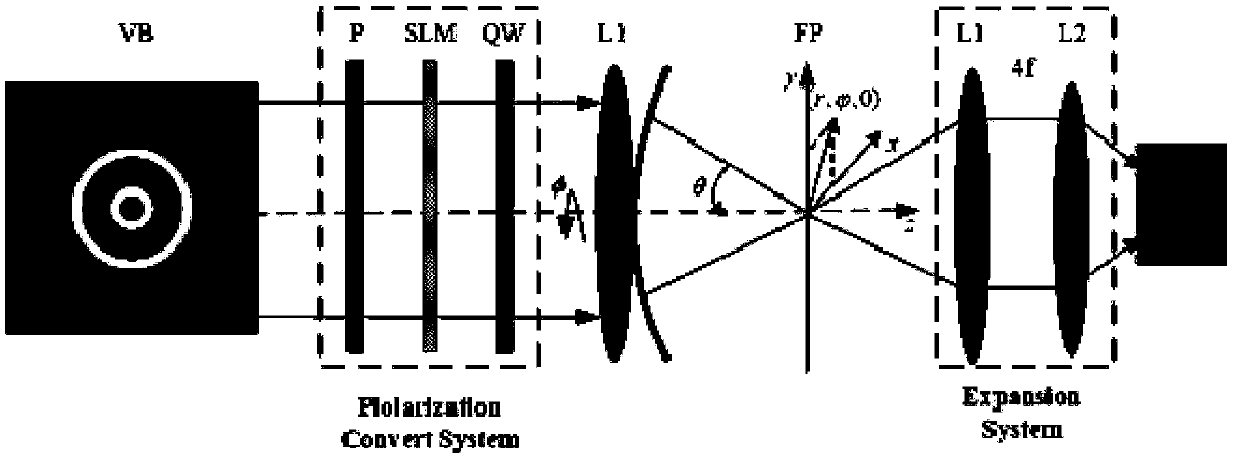
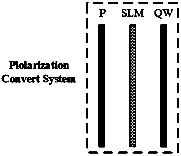
[0019] The present invention provides a method for detecting topological charges using polarization-modulated defocus intensity, such as figure 1 As shown, the process is: the vortex beam to be measured first passes through the polarization modulation system, and the polarization vector of the polarization modulation system is:

[0020]

[0021] in, with respectively represent the unit vectors along the x-axis and y-axis directions on the cross-section of the vortex beam to be measured, and p is the polarization tangential parameter (also called the polarization order), which determines the direction of the polarization state at a certain point in the beam cross-section , which means that when the polarization state rotates from 0 to 2π with the corresponding tangential angle, the polarization direction rotates by the angle pφ, r and φ represent the...


PUM


Abstract

The invention discloses a method for detecting a topological charge by using a polarization modulation defocusing intensity, comprising the following steps of: modulating the vortex beam to be measured through a polarization modulation system; focusing the modulated vortex beam to be measured to its focal region by a high numerical aperture lens; imaging the spot of the focus on the CCD detectionsurface by the 4-f system;gradually increasing the polarization order P of the polarization modulation system, wherein the spot observed on the CCD detection surface exhibits a minimum solid shape when the topological charge of the vortex beam to be measured is equal to the absolute value of the polarization order P value of the polarization modulation system, so that the size of the topological charge l is known; observing the spiral direction of the spot on the CCD detection surface to obtain the direction of the topological charge of the vortex beam to be measured. The method for detectingtopological charge by using polarization modulation defocusing intensity can realize topological charge detection of any polarization vortex beam.

Description

technical field [0001] The invention belongs to the technical field of vortex optics and quantum optics, and specifically relates to a method for detecting topological charge by using polarization modulation defocus intensity. Background technique [0002] Optical vortices have an exp(ilφ) phase term (where φ is the tangential angle, l is the topological charge, which can be any integer), and its phase is unevenly distributed in the cross-section of the beam. Research shows that the angular momentum properties of vortex beams are related to the vortex phase term, where the topological charge l can take any integer. Thus, the angular momentum beams carrying different topological charges constitute an infinitely large orthogonal orbital angular momentum state space, which makes it have the communication potential of a large-capacity channel. Due to their unique angular momentum properties, vortex beams have been successfully applied in various fields such as quantum informati...

Claims


Application Information

Patent Timeline
Patent Type & Authority Applications(China)
IPC IPC(8): G01J11/00G01J4/00
CPCG01J4/00G01J11/00
Inventor 李艳秋戴学兵王叶刘丽辉
Owner BEIJING INSTITUTE OF TECHNOLOGYGY
Why Eureka
Try Eureka