
Generation method and device of detection threshold of moving target

A technology for detecting thresholds and moving targets. It is used in measurement devices, radio wave measurement systems, and radio wave reflection/re-radiation. It can solve the coherence damage between pulses, the submersion of moving targets, and the false alarms of pulse-based radars. problems, to achieve the effect of rapid adaptation and reduction of false alarm rate

Active Publication Date: 2019-04-12
BEIJING INST OF RADIO MEASUREMENT
View PDF6 Cites 7 Cited by
  • Summary
  • Abstract
  • Description
  • Claims
  • Application Information

AI Technical Summary

Problems solved by technology

However, with the development and application of various types of equipment with electromagnetic radiation capabilities, the increasingly complex electromagnetic environment leads to the ubiquity of interference, which will cause the destruction of inter-pulse coherence. When the clutter background and interference exist at the same time, the clutter background The uniformity is destroyed, and the Doppler sidelobe of the clutter causes the moving target to be submerged, which makes it difficult to control the false alarm rate of target detection. This is one of the reasons why the pulse system radar has too many false alarms under interference
In the prior art, there is no method and device for reducing false alarms caused by clutter and interference during detection

Method used


Image

  • Generation method and device of detection threshold of moving target
  • Generation method and device of detection threshold of moving target
  • Generation method and device of detection threshold of moving target

Examples


Embodiment Construction

[0021] The principles and features of the present invention are described below in conjunction with the accompanying drawings, and the examples given are only used to explain the present invention, and are not intended to limit the scope of the present invention.

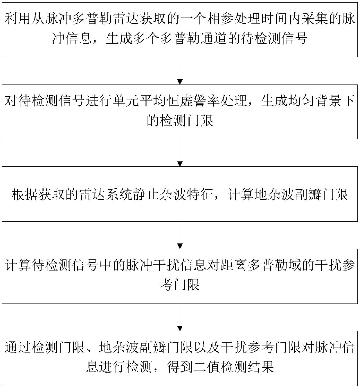
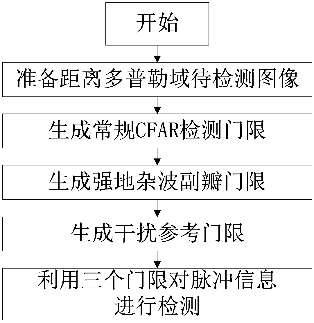
[0022] Such as Figure 1 to Figure 3 as shown, figure 1 It is one of the schematic flowcharts of the threshold generation method provided by the embodiment of the present invention. figure 2 A schematic structural block diagram of a threshold generation device provided by an embodiment of the present invention. image 3 The second schematic flowchart of the threshold generation method provided by the embodiment of the present invention.

[0023] Such as figure 1 As shown, the present invention provides a method for generating a detection threshold of a moving target, which includes:

[0024] Using the pulse information collected within a coherent processing time obtained from the pulse Doppler radar to generate...


PUM


Abstract

The invention provides a generation method of a detection threshold of a moving target. The generation method comprises the steps: to-be-detected signals of a plurality of Doppler channels are generated through pulse information collected within the coherent processing time and obtained from a pulse Doppler radar; the to-be-detected signals are subjected to cell average constant false alarm rate processing to generate the detection threshold under an average background; according to obtained radar system static clutter characteristics, a ground clutter minor lobe threshold is calculated; an interference reference threshold of pulse interference information in the to-be-detected signals to the distance Doppler domain is calculated; and the pulse information is detected through the detectionthreshold, the ground clutter minor lobe threshold and the interference reference threshold, and a two-value detection result is obtained. On the basis of a cell average constant false alarm rate method, the false alarm rate caused by clutter and interference during detection is decreased by combining static clutter distribution and interference distribution of current data with generation of thecoherent characteristic optimized detection threshold of a radar system.

Description

technical field [0001] The invention relates to the technical field of radar system and radar signal processing, in particular to a method and device for generating a detection threshold of a moving target. Background technique [0002] Radar has the ability to find targets all-weather and all-weather. PD (Pulse Doppler, Pulse Doppler) coherent system radar is widely used because of its good clutter suppression ability. However, with the development and application of various types of equipment with electromagnetic radiation capabilities, the increasingly complex electromagnetic environment leads to the ubiquity of interference, which will cause the destruction of inter-pulse coherence. When the clutter background and interference exist at the same time, the clutter background The uniformity is destroyed, and the Doppler sidelobe of clutter causes the moving target to be submerged, which makes it difficult to control the false alarm rate of target detection. This is one of t...

Claims


Application Information

Patent Timeline
IPC IPC(8): G01S13/50G01S7/36G01S7/292
CPCG01S7/2927G01S7/36G01S13/50Y02A90/10
Inventor 景凯田超卢博尚悦
Owner BEIJING INST OF RADIO MEASUREMENT
Learn More