
Filter and manufacturing method thereof

A filter and resonator technology, which is applied in waveguide devices, electrical components, circuits, etc., can solve the problems of large filter size and difficulty in realizing multi-chip integration, and achieve small size, improved out-of-band rejection, and widened bandwidth Effect

Pending Publication Date: 2019-04-12
GUANGDONG DAPU TELECOM TECH CO LTD
View PDF0 Cites 2 Cited by
  • Summary
  • Abstract
  • Description
  • Claims
  • Application Information

AI Technical Summary

Problems solved by technology

[0004] The embodiment of the present invention provides a filter and its manufacturing method to solve the problem that the existing filter has a large volume and is difficult to realize multi-chip integration

Method used


Image

  • Filter and manufacturing method thereof
  • Filter and manufacturing method thereof
  • Filter and manufacturing method thereof

Examples


Embodiment Construction

[0031] The present invention will be further described in detail below in conjunction with the accompanying drawings and embodiments. It should be understood that the specific embodiments described here are only used to explain the present invention, but not to limit the present invention. In addition, it should be noted that, for the convenience of description, only some structures related to the present invention are shown in the drawings but not all structures.

[0032] An embodiment of the present invention provides a filter, including:

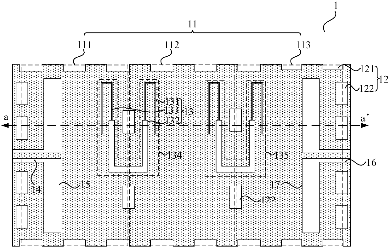
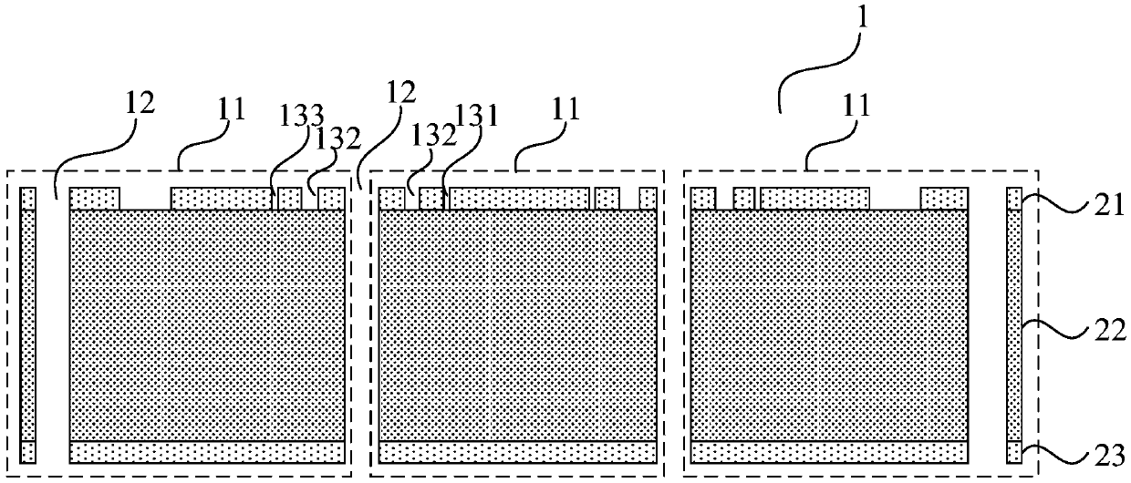
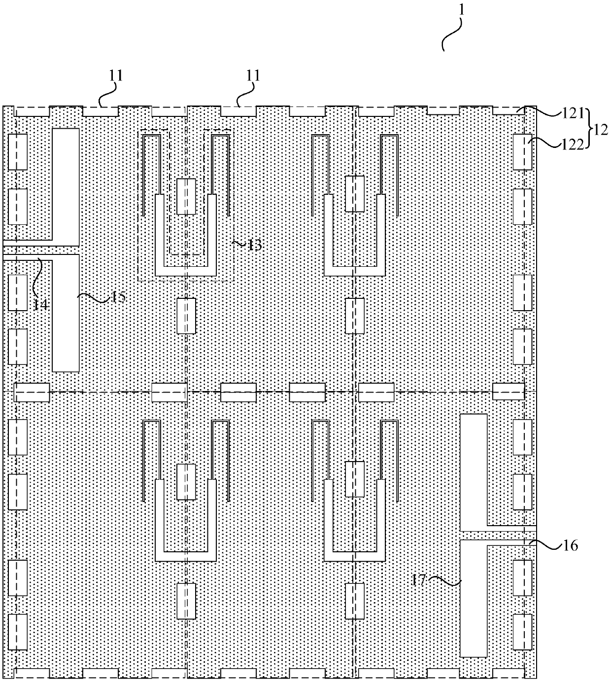
[0033] At least one silicon cavity resonant unit, the silicon cavity resonant unit includes a bottom metal layer, a high-resistance silicon dielectric layer and a top metal layer arranged in sequence; multiple penetrating structures are arranged on the edge of each silicon cavity resonating unit; the penetrating structure runs through the bottom metal layer 1. A high-resistance silicon dielectric layer and a top metal layer; a metal depo...


PUM

PropertyMeasurementUnit
lengthaaaaaaaaaa
widthaaaaaaaaaa
widthaaaaaaaaaa

Abstract

The invention discloses a filter and a manufacturing method thereof, the filter comprises at least one silicon cavity resonance unit, and the silicon cavity resonance unit comprises a bottom metal layer, a high-resistance silicon dielectric layer and a top metal layer which are sequentially arranged. The edge of each silicon cavity resonance unit is provided with a plurality of through structures.The through structure penetrates through the bottom metal layer, the high-resistance silicon dielectric layer and the top metal layer. A metal deposition layer is formed on the surface of the inner side of the through structure. The penetrating structure is a through hole and / or a through groove. A slot line type stepped impedance resonator is also included and is composed of a plurality of slotlines which are formed on the top metal layer and communicate with one another. The depth of the slot line is equal to the thickness of the top metal layer. According to the filter and the manufacturing method thereof, the problems that an existing filter is large in size and multi-chip integration is not easy to achieve are solved.

Description

technical field [0001] The invention relates to the technical field of miniaturized filters, in particular to a filter and a manufacturing method thereof. Background technique [0002] Filters play an important role in frequency selective filtering in radio frequency and microwave systems. Specifically, filters can pass electrical signals of a certain frequency and block other frequencies. The main performance indicators of filters include insertion loss, bandwidth, out-of-band selectivity, and circuit size, etc. Bandwidth expansion and circuit miniaturization have always been the key design difficulties of filters. [0003] Traditional filters include cavity filters, LC filters and planar filters. The cavity filter is formed by cutting metal as a whole, the LC filter is composed of a combination of inductors, capacitors and resistors, and the planar filter is composed of transmission lines and PCB boards. However, there are problems such as large size and difficulty in int...

Claims


Application Information

Patent Timeline
Patent Type & Authority Applications(China)
IPC IPC(8): H01P1/207H01P1/208H01P11/00
CPCH01P1/207H01P1/208H01P11/007
Inventor 万晶梁晓新阎跃鹏王霄邱文才
Owner GUANGDONG DAPU TELECOM TECH CO LTD
Learn More