Differential-type connector for transmission

A connector and differential technology, applied in the field of differential transmission connectors, can solve the problems of difficulty in ensuring accuracy, difficult to simulate, and affect signal quality, so as to improve signal transmission speed, facilitate mass production, and improve transmission. effect of speed

Active Publication Date: 2019-04-12
DONGGUAN DINGTONG PRECISION METAL CO LTD
View PDF5 Cites 0 Cited by
  • Summary
  • Abstract
  • Description
  • Claims
  • Application Information

AI Technical Summary

Problems solved by technology

[0002] In a multi-pole connector for high-speed differential signal transmission, if the differential signal terminals and other terminals (such as external terminals such as power terminals and ground terminals (that is, terminals other than pairs of terminals)) are arranged at equal intervals , the bonding force between differential pairs cannot be fully ensured, and the transmission mode is closer to single mode
Compared with differential mode transmission, single-mode transmission has poorer characteristics such as signal speed, skew, and noise, and if the pitch is simply reduced to strengthen the above-mentioned bonding force, the impedance will be relatively set due to the influence of other terminals. The impedance or rated value is too low, so it is difficult to realize the differential mode transmission at equal intervals in the connector part of the differential impedance of the 100Q series. The existing technology changes the width of the differential signal terminal or bends the differe

Method used


Image

  • Differential-type connector for transmission
  • Differential-type connector for transmission
  • Differential-type connector for transmission

Examples


Embodiment Construction

[0021] The following will clearly and completely describe the technical solutions in the embodiments of the present invention with reference to the accompanying drawings in the embodiments of the present invention. Obviously, the described embodiments are only some, not all, embodiments of the present invention. Based on the embodiments of the present invention, all other embodiments obtained by persons of ordinary skill in the art without making creative efforts belong to the protection scope of the present invention.

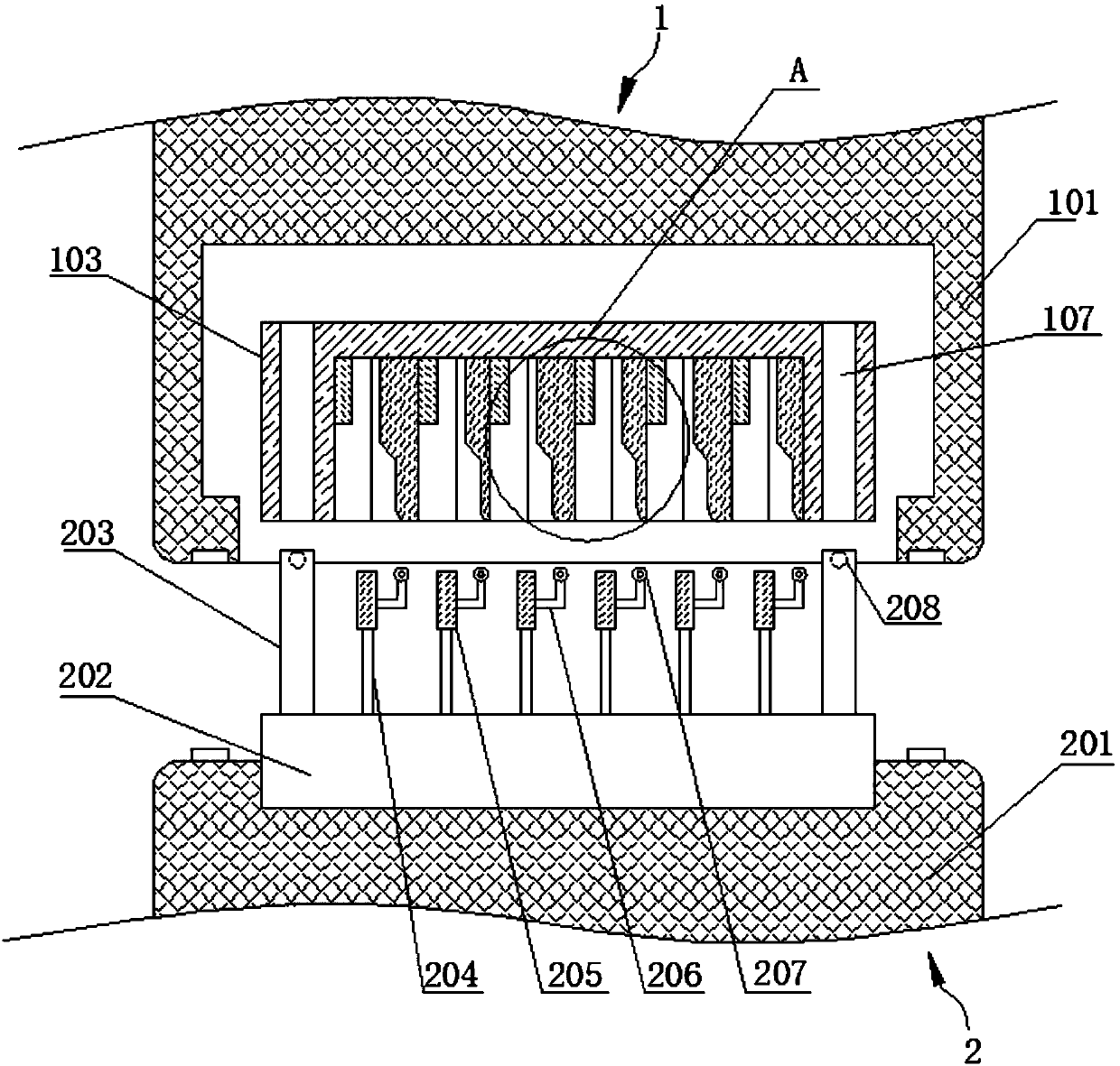
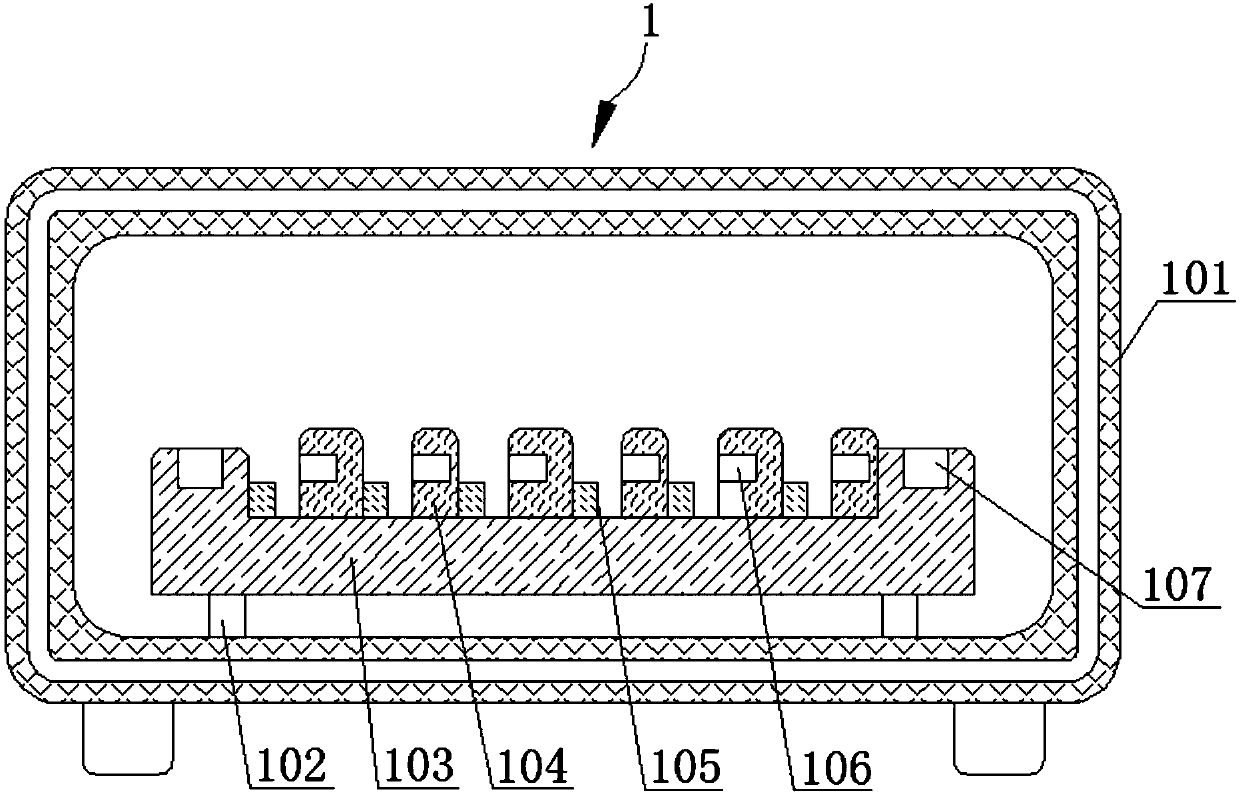
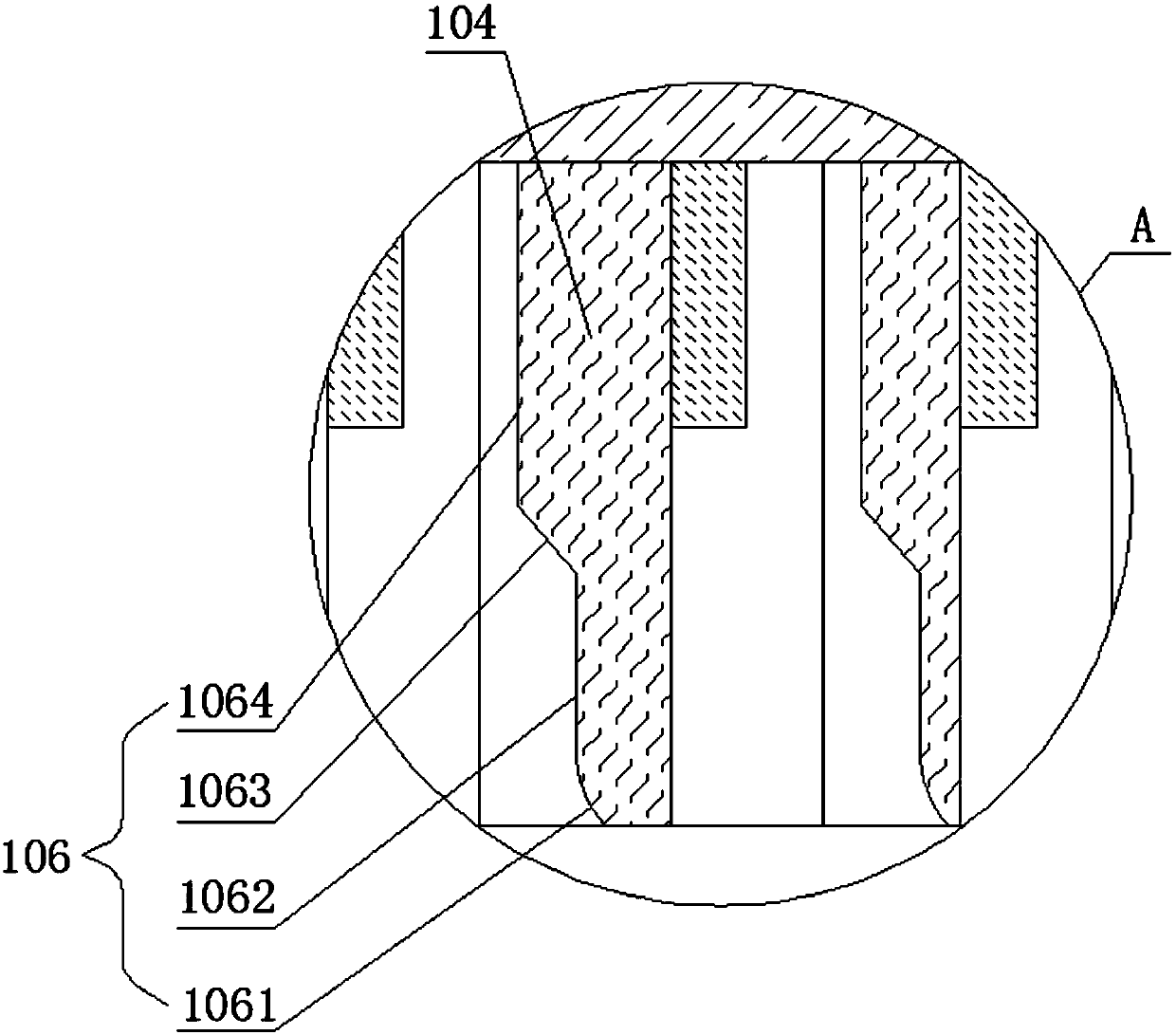
[0022] see Figure 1-3 , the present invention provides a technical solution:

[0023] A differential transmission connector, comprising a female plug 1 and a mating male plug 2, the lower end of the female plug 1 is electrically connected to the electromagnetic shielding layer of the printed circuit board through the supporting legs, and a row of The elastic rods 204 are arranged equidistantly and can change the position of the male and female contact termin...


PUM


Abstract

The invention relates to the technical field of connectors, in particular to a differential-type connector for transmission. A row of elastic rods are arranged on a male plug, are equally arranged andcan be used for changing a position of a male plug contact terminal, a female plug comprises a female plug shell, a terminal support part and a female plug contact terminal, the terminal support partis fixedly connected with an accommodating cavity in an opening end of the female plug shell by welding, an accommodating groove is formed in an upper end surface of the terminal support part and isused for placing the female plug contact terminal, two groups of terminal blocking plates with same height and different widths are equally connected in the accommodating groove, a plurality of femaleplug contact terminals are arranged in the accommodating groove and are arranged between adjacent terminal blocking plates, and a sliding groove is formed in one side, near to the female plug contactterminal, of each terminal blocking plate. By the differential-type connector for transmission, the clamping sealing performance of the male plug and the female plug is improved, the interference ofexternal air is reduced, the transmission rate is improved, and the differential-type connector for transmission has the remarkable substantive characteristic and the remarkable progress.

Description

technical field [0001] The invention relates to the technical field of connectors, in particular to a differential transmission connector. Background technique [0002] In a multi-pole connector for high-speed differential signal transmission, if the differential signal terminals and other terminals (such as external terminals such as power terminals and ground terminals (that is, terminals other than pairs of terminals)) are arranged at equal intervals , the bonding force between the differential pairs cannot be fully ensured, and the transmission mode is closer to single mode. Compared with differential mode transmission, single-mode transmission has poorer characteristics such as signal speed, skew, and noise, and if the pitch is simply reduced to strengthen the above-mentioned bonding force, the impedance will be relatively set due to the influence of other terminals. The impedance or rated value is too low, so it is difficult to realize the differential mode transmissi...

Claims


Application Information

Patent Timeline
IPC IPC(8): H01R12/70H01R12/71H01R13/629H01R13/15H01R13/639H01R13/52
CPCH01R12/7011H01R12/716H01R13/15H01R13/5219H01R13/629H01R13/639
Inventor 曹明旭
Owner DONGGUAN DINGTONG PRECISION METAL CO LTD
Why Eureka
Try Eureka