Boosting circuit and terminal

A boost circuit and terminal technology, applied in circuit devices, battery disconnect circuits, battery circuit devices, etc., can solve problems affecting the accuracy of over-current detection, improve the accuracy of over-current detection, reduce thermal power consumption, and conduct The effect of low resistance

Inactive Publication Date: 2019-04-12
VIVO MOBILE COMM CO LTD
View PDF5 Cites 1 Cited by
  • Summary
  • Abstract
  • Description
  • Claims
  • Application Information

AI Technical Summary

Problems solved by technology

[0004] The embodiment of the present invention provides a boost circuit and terminal to solve the problem in the prior art that the transistors in the charging and discharging path affect the accuracy of overcurrent detection

Method used


Image

  • Boosting circuit and terminal
  • Boosting circuit and terminal
  • Boosting circuit and terminal

Examples


Embodiment 1

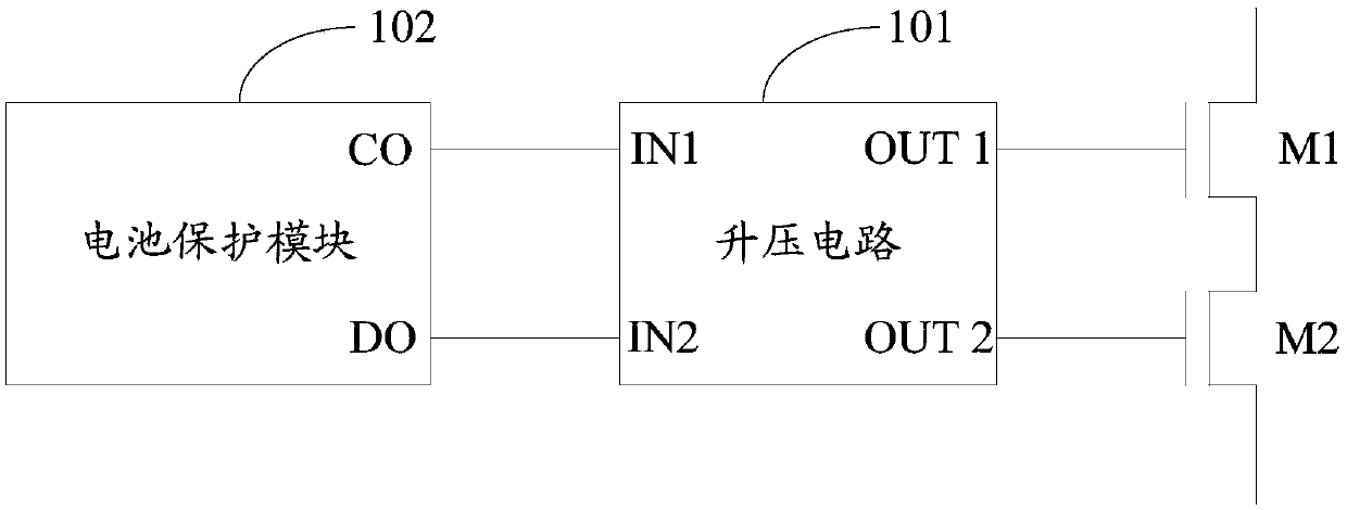
[0021] refer to figure 1 , shows a schematic structural diagram of a boost circuit provided by an embodiment of the present invention. Applied to a terminal with a rechargeable battery, the terminal includes a battery protection module 102, a first transistor M1 and a second transistor M2;

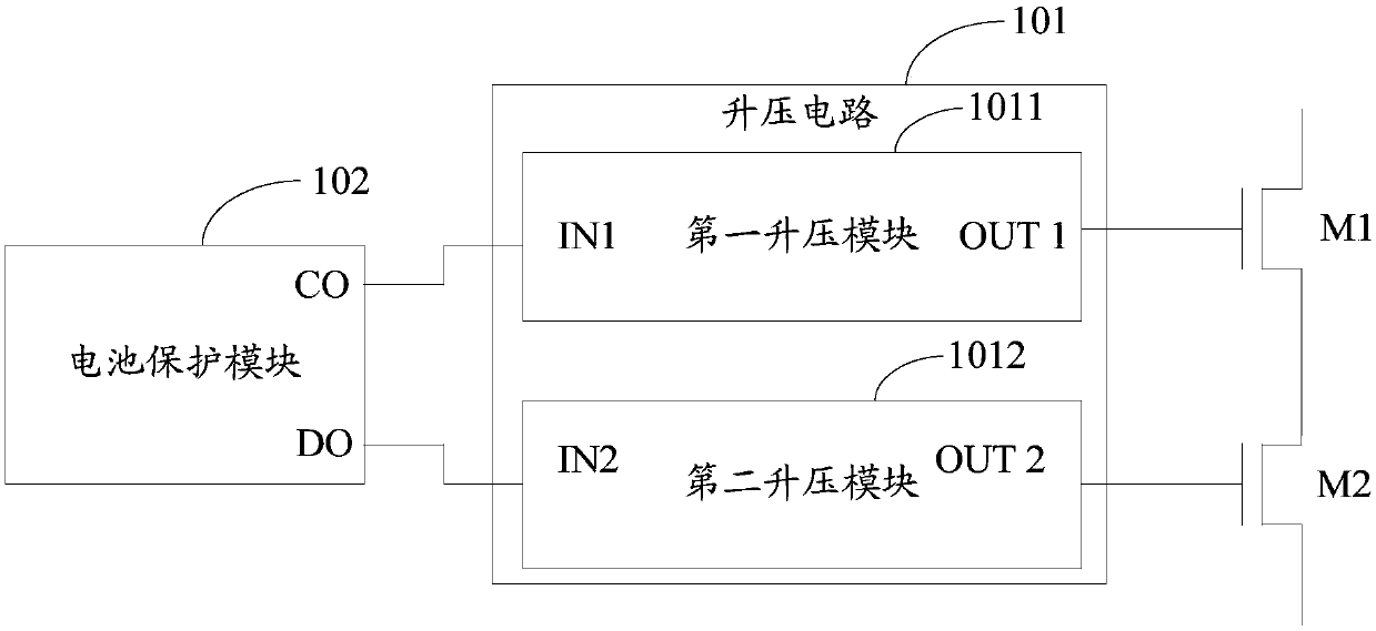
[0022] The first input terminal IN1 of the boost circuit 101 is connected to the charge control CO terminal of the battery protection module 102, the second input terminal IN2 is connected to the discharge control DO terminal of the battery protection module 102, and the first output terminal OUT1 connected to the control electrode of the first transistor M1, and the second output terminal OUT2 is connected to the control electrode of the second transistor M2;

[0023] The boost circuit 101 is configured to boost the driving voltage output by the CO terminal and the DO terminal under the condition that the first transistor M1 and the second transistor M2 are controlled to be turned on, so...

Embodiment 2

[0047] refer to Figure 4 , shows a structural block diagram of a terminal provided by an embodiment of the present invention. The terminal includes a rechargeable battery 103, a battery protection module 102, a first transistor M1, a second transistor M2, a first resistor R1 and a boost circuit 101 as described in Embodiment 1;

[0048] The first power supply terminal VDD of the battery protection module 102 is connected to the first power supply terminal P+ of the terminal and the first electrode B+ of the rechargeable battery, and the second power supply terminal VSS is connected to the second electrode B- of the rechargeable battery. connection, the charge control CO terminal is connected to the first input terminal IN1 of the boost circuit 101, the discharge control DO terminal is connected to the second input terminal IN2 of the boost circuit 101, and the detection terminal VM is connected to the first resistor R1 connected to one terminal; the battery protection module...


PUM


Abstract

The invention provides a boosting circuit and a terminal. The boosting circuit is applied to the terminal having a rechargeable battery; the terminal comprises a battery protection module, a first transistor and a second transistor; a first input end of the boosting circuit is connected with a charging control CO (Carbon Oxide) end of the battery protection module; a second input end of the boosting circuit is connected with a discharge control DO (Dissolved Oxygen) end of the battery protection module; a first output end of the boosting circuit is connected with a control electrode of the first transistor; a second output end of the boosting circuit is connected with the control electrode of the second transistor; and the boosting circuit is used for boosting driving voltages outputted bythe CO end and the DO end in a case where the first transistor and the second transistor are controlled to be switched on so as to reduce the on-resistance of the first transistor and the second transistor. According to the embodiment provided by the invention, the on-resistance of the first transistor and the second transistor can be enabled to be lower and more stable, thereby implementing theeffect of reducing the thermal power consumption of the channel and improving the over-current detection precision.

Description

technical field [0001] The invention relates to the technical field of charging and discharging, in particular to a voltage boosting circuit and a terminal. Background technique [0002] With the development of fast charging technology, the application of the fast charging function in terminal devices is becoming more and more popular, and the terminal devices with fast charging are very popular among users. In order to provide users with a faster and more extreme charging experience, the charging current is getting bigger and bigger. In order to protect the battery, over-current detection is required. The process of overcurrent detection includes: detecting the gate-source voltage of the transistor on the charging and discharging path. When the gate-source voltage of the transistor exceeds the set threshold of overcurrent protection, it is determined that there is an overcurrent, and the transistor is controlled to turn off to protect the battery. [0003] Generally, the p...

Claims


Application Information

Patent Timeline
Patent Type & Authority Applications(China)
IPC IPC(8): H02J7/00
CPCH02J7/00304H02J7/0031
Inventor 陈光辉
Owner VIVO MOBILE COMM CO LTD
Why Eureka
Try Eureka