Supercharge Your Innovation With Domain-Expert AI Agents!

Rotor support structure of permanent magnet spherical motor

A spherical motor and rotor support technology, applied in the direction of magnetic circuit shape/style/structure, magnetic circuit rotating parts, etc., can solve the problems of small output torque, stator spherical shell collision, poor stability, etc., to reduce the contact area , reduce friction, high reliability

Active Publication Date: 2019-04-12
ANHUI UNIVERSITY
View PDF5 Cites 3 Cited by
  • Summary
  • Abstract
  • Description
  • Claims
  • Application Information

AI Technical Summary

Problems solved by technology

The existing defects are: 1. Only one universal ball is installed at the bottom center of the stator spherical shell, and the structural stability is poor. When the rotor moves, it is very easy to cause the rotor body to tilt sideways and collide with the stator spherical shell
It not only affects the normal movement of the rotor body, but also causes damage to the motor; 2. Installing a number of universal balls forming a circular ring on the bottom side of the stator spherical shell also has the disadvantage of poor stability, and the use of a convex support column will cause excessive friction 3. Designing the rotor body as hemispherical will sacrifice the number of permanent magnets and the integrity of the arrangement, which will affect the output torque and the movement range and accuracy of the rotor body

Method used


Image

  • Rotor support structure of permanent magnet spherical motor
  • Rotor support structure of permanent magnet spherical motor
  • Rotor support structure of permanent magnet spherical motor

Examples


Embodiment Construction

[0022] The present invention will be further described below in conjunction with the accompanying drawings and embodiments.

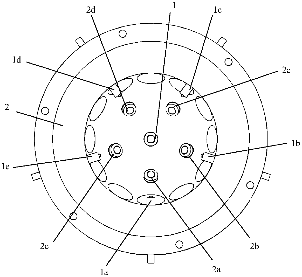
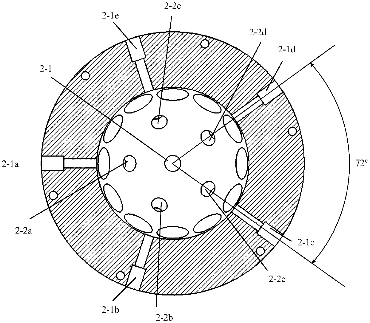
[0023] refer to Figure 1 to Figure 4 , a permanent magnet spherical motor rotor support structure, characterized in that the support structure includes an equatorial surface support column group, a side support column group, a bottom surface support column 1, and a stator lower casing 2. The equatorial support column group includes five identical equatorial support columns, namely the first equatorial support column 1a, the second equatorial support column 1b, the third equatorial support column 1c, the fourth equatorial support column 1d, the Five equatorial support columns 1e, installed in the first mounting hole 2-1a, the second mounting hole 2-1b, the third mounting hole 2-1c, the fourth mounting hole 2-1d, the fifth Mounting hole 2-1e. The side support column group includes 5 identical side support columns, namely the first side support column 2...


PUM


Abstract

The invention discloses a rotor support structure of a permanent magnet spherical motor. The support structure comprises a bottom support column, a side support column group, an equatorial plane support column group and a lower stator shell. The equatorial plane support column group comprises five identical equatorial plane support columns, which are installed at designated positions of the equatorial plane of the lower stator shell. The side support column group comprises five identical side support columns, which are installed at designated positions of the side face of the lower stator shell. The bottom support column is the same as the side support column in terms of structure, and is installed at the center point of the bottom surface of the lower stator shell. Mounting holes are leftin the lower stator shell corresponding to the support columns. The equatorial plane support columns can prevent side slanting caused by high-speed motion of the rotor, and at the same time, on the head of the equatorial plane support column, a ball-head plunger with a spring is adopted to suppress shaking when the rotor moves, and the contact area between the support column and the rotor body isreduced, thereby reducing the friction force. The rotor can be supported to work normally after one or more support columns are damaged, and the reliability is high.

Description

technical field [0001] The invention relates to the technical field of spherical motors, in particular to a permanent magnet spherical motor rotor support structure. Background technique [0002] With the rapid development of industrial manufacturing and the sharp rise of labor costs, robots, robotic arms, panoramic cameras and other devices that can realize high-precision servo motion in multi-dimensional space have been widely needed and applied. In order to achieve multi-degree-of-freedom motion, multiple single-degree-of-freedom motors are usually used in conjunction with mechanical transmission mechanisms to cooperate with each other, resulting in increased system volume and weight, reduced mechanical reliability, and poor dynamic performance. Therefore, researchers at home and abroad have proposed a spherical motor that can realize multi-degree-of-freedom motion. Among them, the permanent magnet spherical motor has attracted more attention due to its simple structure, ...

Claims


Application Information

Patent Timeline
IPC IPC(8): H02K1/28
CPCH02K1/28
Inventor 李国丽文彦王群京过希文付冠东
Owner ANHUI UNIVERSITY
Features
  • R&D
  • Intellectual Property
  • Life Sciences
  • Materials
  • Tech Scout
  • Unparalleled Data Quality
  • Higher Quality Content
  • 60% Fewer Hallucinations
Learn More