Power electronic transformer circuit, power electronic transformer and control method

A transformer circuit and power electronics technology, which is applied in the direction of electrical components, AC power input conversion to AC power output, and AC power input conversion to DC power output, etc., can solve the problem of increasing the size of power electronic transformers, which is not conducive to long-term development and unfavorable system simplification issues such as

Active Publication Date: 2019-04-12
SUZHOU UNIV
View PDF6 Cites 3 Cited by
  • Summary
  • Abstract
  • Description
  • Claims
  • Application Information

AI Technical Summary

Problems solved by technology

[0008] To sum up, in the power electronic transformer circuit in the prior art, due to the pulsating power introduced by the AC input, a larger capacitor has to be used to store the pulsating power to prevent the pulsating power from damaging the circuit, thereby increasing the overall power electronic capacity. The size of the transformer is not conducive to the simplification of the system, which is not conducive to the long-term development

Method used


Image

  • Power electronic transformer circuit, power electronic transformer and control method
  • Power electronic transformer circuit, power electronic transformer and control method
  • Power electronic transformer circuit, power electronic transformer and control method

Examples


Embodiment Construction

[0066] The core of the present invention is to provide a power electronic transformer circuit, a power electronic transformer and a control method of the power electronic transformer, which are used to reduce the volume of the required capacitor under the premise of avoiding damage to the grid circuit by pulsating power.

[0067] The following will clearly and completely describe the technical solutions in the embodiments of the present invention with reference to the accompanying drawings in the embodiments of the present invention. Obviously, the described embodiments are only some, not all, embodiments of the present invention. Based on the embodiments of the present invention, all other embodiments obtained by persons of ordinary skill in the art without making creative efforts belong to the protection scope of the present invention.

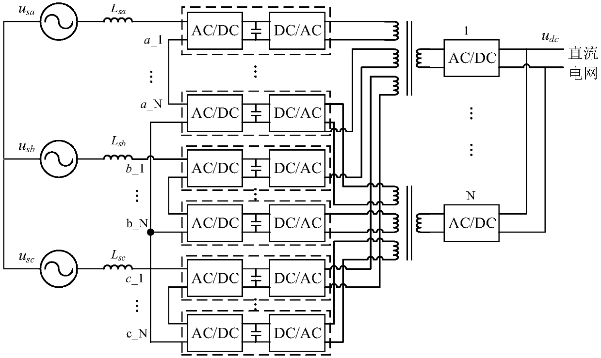
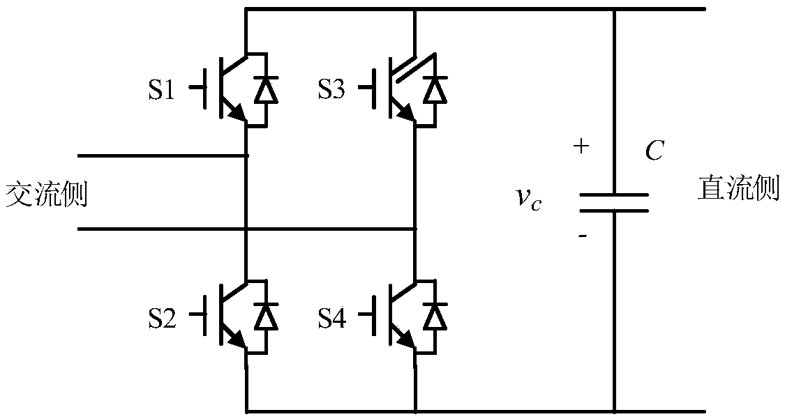
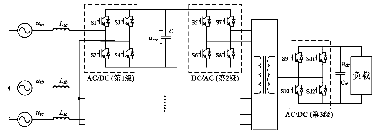
[0068] figure 1 A circuit diagram of a power electronic transformer circuit provided by an embodiment of the present invention; figure 2 ...


PUM


Abstract

The invention discloses a power electronic transformer circuit, a power electronic transformer and a control method of the power electronic transformer; a multi-winding transformer is arranged among acascade H bridge and an inversion H bridge connected with a three-phase alternating current power grid, and a rectifying H bridge arranged at the input end of a direct current power grid; the input end of the multi-winding transformer is connected with H bridge modules connected from a three-phase alternating-current power grid; the input power of each H bridge module comprises a direct-current component and a secondary pulsation component, and the secondary pulsation power is in a rule of three-phase symmetry and negative sequence; after the multi-winding transformer is input from the threeH bridge modules, the output power of the multi-winding transformer is equal to the synthesis of input power of three ports according to the power balance relation, the secondary pulsation power is counteracted, and only the direct current component is transmitted to the direct current output end. A direct-current capacitor in the cascaded H bridge does not need to store pulse power, and the volume of the direct-current capacitor can be remarkably reduced, so that the size of the power electronic transformer is reduced, and the voltage and current stress of the power device is reduced.

Description

technical field [0001] The invention relates to the technical field of power electronics, in particular to a power electronic transformer circuit, a power electronic transformer and a control method for the power electronic transformer. Background technique [0002] Compared with the traditional line frequency transformer (Line Frequency Transformer, LFT), the power electronic transformer (power electronics transformer, PET) can not only significantly reduce the volume and weight of the transformer and passive filter components in the system, but also realize reactive power compensation, harmonic Wave compensation, power flow control, redundant backup, power system failure protection and other functions are one of the key technologies in the development of smart grid. Power electronic transformers are not only suitable for traditional AC / AC power conversion, but also for AC / DC grid interconnection. In high-voltage, high-power AC / DC applications, power electronic transformer...

Claims


Application Information

Patent Timeline
Patent Type & Authority Applications(China)
IPC IPC(8): H02M5/458H02M7/219
CPCH02M5/4585H02M7/219H02M1/007
Inventor 何立群李晓辉谢门喜杨勇樊明迪
Owner SUZHOU UNIV
Why Eureka
Try Eureka