System and method for ultra-low emission of boiler flue gas

A boiler flue gas and emission system technology, applied in chemical instruments and methods, separation methods, gas treatment, etc., can solve the problems of unmentioned flue gas denitration treatment technology, short service life of high-temperature SCR catalysts, and increased denitration costs, etc. Achieve the effect of improving energy utilization efficiency, reducing denitration costs, and improving boiler thermal efficiency

Active Publication Date: 2020-10-09
JIANGSU LONGKING COALOGIX CATALYST REGENERATION CO LTD
View PDF2 Cites 0 Cited by
  • Summary
  • Abstract
  • Description
  • Claims
  • Application Information

AI Technical Summary

Problems solved by technology

Patent (CN108126508A) discloses an ultra-low emission desulfurization and dust removal integrated device, but the invention does not mention flue gas denitrification treatment technology; patent (CN206989168U) provides a boiler flue gas ultra-low emission device, including coal-fired boilers, Denitration reactor, bag filter and desulfurization tower. However, this technology uses high-temperature denitration, and the high-temperature SCR catalyst has a short service life, which will increase the cost of denitration

Method used


Image

  • System and method for ultra-low emission of boiler flue gas

Examples


Embodiment 1

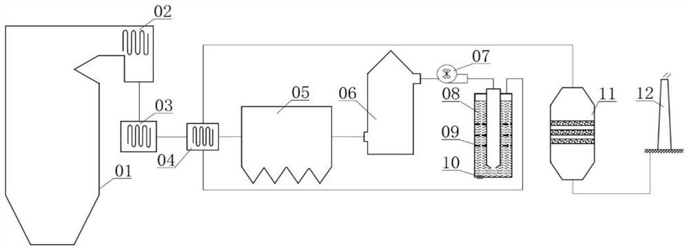
[0029] Such as figure 1 As shown, it is a schematic diagram of a boiler flue gas ultra-low emission system in this embodiment. The boiler flue gas ultra-low emission system includes a furnace 01, an economizer 02, an air preheater 03, a heat exchanger 04, and a dust collector 05. Desulfurization tower 06, induced draft fan 07, cleaning device 08, denitrification reactor 11 and chimney 12;

[0030] The furnace 01, the economizer 02, the air preheater 03, the heat exchanger 04, the dust collector 05, the desulfurization tower 06, the induced draft fan 07 and the cleaning device 08 connected in sequence; wherein, the heat exchanger 04 includes a first gas inlet for connecting with the air preheater 3 and a first gas outlet for connecting with the dust remover 05; the first gas The inlet and the first gas outlet are connected through a first flue gas pipe;

[0031] The heat exchanger 04 also includes a second gas inlet connected to the gas outlet of the cleaning device 08 and a ...

Embodiment 2

[0037] This embodiment provides a method for ultra-low emission of boiler flue gas, adopting the ultra-low emission system of boiler flue gas described in Embodiment 1; the method is:

[0038] The boiler flue gas first passes through the economizer 02, the air preheater 03 and the heat exchanger 04 and enters the dust collector 05 at a temperature of 130°C, the temperature of the flue gas exiting the dust collector 05 is 85°C, and the smoke concentration is 10mg / Nm 3 (In this embodiment, the dust collector 05 adopts a bag filter). The flue gas after dedusting enters the desulfurization tower 06, and the SO in the flue gas after desulfurization 2 The concentration is 14mg / Nm 3 , The temperature is 52 ℃. After desulfurization, the flue gas is sent to the cleaning device 08 by the induced draft fan 07, and the potassium hydroxide solution is used to further absorb the residual dust and SO 2, the dust concentration in the flue gas after cleaning is 2 mg / Nm 3 , SO 2 The concen...

Embodiment 3

[0040] This embodiment provides a method for ultra-low emission of boiler flue gas, adopting the ultra-low emission system of boiler flue gas described in Embodiment 1; the method is:

[0041] The boiler flue gas first passes through the economizer 02, the air preheater 03 and the heat exchanger 04 and enters the dust collector 05 at a temperature of 140°C, the temperature of the flue gas exiting the dust collector 05 is 90°C, and the smoke concentration is 12mg / Nm 3 (In this embodiment, the dust collector 05 adopts an electric bag dust collector). The flue gas after dedusting enters the desulfurization tower 06, and the SO in the flue gas after desulfurization 2 The concentration is 16mg / Nm 3 , The temperature is 54 ℃. After desulfurization, the flue gas is sent to the cleaning device 08 by the induced draft fan 07, and the sodium hydroxide solution is used to further absorb the residual dust and SO 2 , the dust concentration in the flue gas after cleaning is 2 mg / Nm 3 , ...


PUM


Abstract

The invention mainly belongs to the technical field of air pollutant control, and in particular relates to a system and method for ultra-low emission of boiler flue gas. The system includes a furnace, an economizer, an air preheater, a heat exchanger, a dust collector, a desulfurization tower, an induced draft fan, a cleaning device, a denitrification reactor and a chimney. The method is that the boiler flue gas enters the dust collector through the economizer, the air preheater and the heat exchanger, enters the desulfurization tower after dedusting, and is sent to the cleaning device by the induced draft fan after desulfurization, and the flue gas is heated by the heat exchanger after being cleaned and enters the desulfurization tower. The denitrification reactor is finally discharged through the chimney. The boiler flue gas ultra-low emission system and method provided by the present invention can realize the soot concentration ≤ 5mg / Nm 3 , SO 2 Concentration≤35mg / Nm 3 and NO x Concentration≤50mg / Nm 3 ultra-low emission requirements.

Description

technical field [0001] The invention belongs to the technical field of air pollutant control, and in particular relates to a system and method for ultra-low discharge of boiler flue gas. Background technique [0002] In 2017, coal accounted for 27.6% of global primary energy consumption and 60.4% of China's energy structure. It is the main fuel in China's energy consumption, and the thermal power industry is the main area of ​​coal consumption. Smoke, sulfur dioxide (SO 2 ) and nitrogen oxides (NO x ) is an important source of air pollutants. [0003] The state's emphasis on air pollution control has put forward higher technical requirements for relevant enterprises to achieve ultra-low emissions of boiler flue gas in coal-fired power plants. For technological transformation to achieve ultra-low emissions, it is necessary to take into account combustion efficiency, input costs, and smoke, SO 2 and NO x emissions. Patent (CN108126508A) discloses an ultra-low emission de...

Claims


Application Information

Patent Timeline
Patent Type & Authority Patents(China)
IPC IPC(8): B01D53/75B01D53/86B01D53/56B01D53/78B01D53/50B01D50/00
CPCB01D50/00B01D53/50B01D53/502B01D53/75B01D53/78B01D53/8625B01D2258/0283B01D50/60
Inventor 张深根张柏林刘波
Owner JIANGSU LONGKING COALOGIX CATALYST REGENERATION CO LTD
Why Eureka
Try Eureka