Punching device

A punching device and punching technology, applied in the field of punching, can solve the problems of affecting the brazing quality, low product qualification rate, deviation of the branch tube core and the flanging hole core, etc.

Pending Publication Date: 2019-04-16
安徽省三荣科技有限公司
View PDF0 Cites 6 Cited by
  • Summary
  • Abstract
  • Description
  • Claims
  • Application Information

AI Technical Summary

Problems solved by technology

In the prior art, punching and flanging are usually carried out from the lumen of the pipe A to be punched outward by using a punching die, such as figure 1 As shown, an external flange hole is formed on the pipe wall of the pipe A to be punched, and then the branch pipe is inserted into the flange hole for brazing. In order to ensure the insertion depth of the branch pipe, it is generally welded on the pipe wall at the insertion end of the branch pipe Limiting bumps, when plugging in, make the limiting bumps on the branch

Method used


Image

  • Punching device
  • Punching device
  • Punching device

Examples


Embodiment Construction

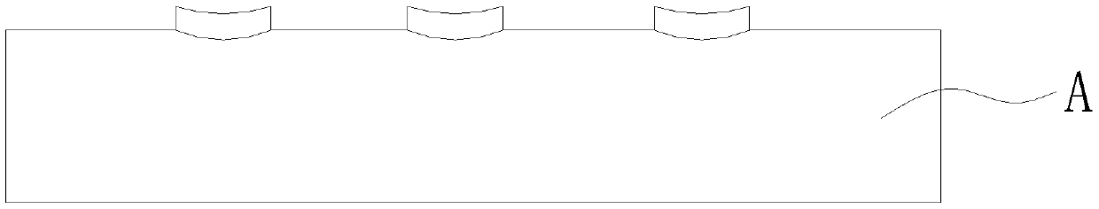
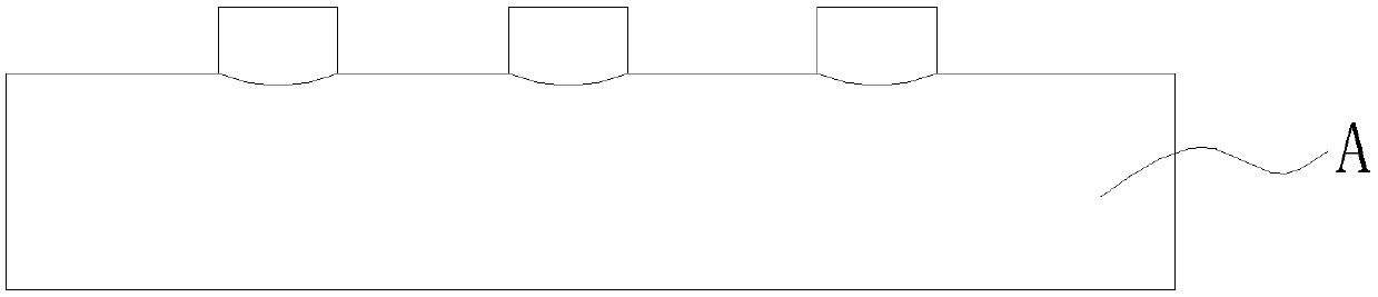
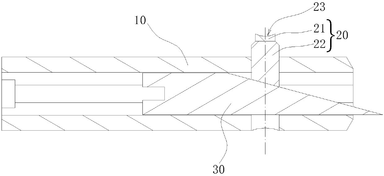
[0012] In conjunction with the accompanying drawings, a punching device includes a tube mold 10 inserted into the lumen of the pipe A to be punched, and a punch 20 is provided at the through hole provided on the tube wall of the tube mold 10, and the punch 20 is placed on the tube wall of the tube mold 10. Protruding and retracting movements are made in the through hole perpendicular to the direction of the pipe die 10. The end 21 of the punch 20 outside the pipe die 10 is an elliptical column whose long axis is consistent with the direction of the pipe die 10. The end surface is concave. The curved punching surface 23 and the center line of curvature of the concave arc punching surface 23 are perpendicular to the tube core of the pipe mold 10 . In the present invention, the end face of the end 21 of the punch 20 is set as a concave arc-shaped punching surface 23, so that the contour of the end 21 of the punch 20 can form a knife edge, so as to be used for shearing the wall of ...


PUM


Abstract

The invention discloses a punching device. The punching device comprises a pipe mold inserted into a pipe cavity of a to-be-punched pipe, a punch is arranged at a through hole formed in the pipe wallof the pipe mold, the punch does stretching and retracting movement perpendicular to the pipe core direction of the pipe mold in the through hole, the end part of the portion, located outside the pipemold, of the punch is a concave arc-shaped punching surface which is of an oval columnar shape with the long axis consistent with the direction of the pipe core of the pipe mold, the end face of theportion is a concave arc-shaped punching surface, and the curvature center line of the concave arc-shaped punching surface is perpendicular to the pipe core of the pipe mold. Under the matching actionof an oval columnar column body of the end part of the punch and the concave arc-shaped punching surface, a notch in the pipe wall of the to-be-punched pipe is oval after the to-be-punched pipe is punched, and the long axis of the oval is consistent with the direction of the pipe core of the to-be-punched pipe, so that the size of the notch in the pipe wall of the to-be-punched pipe in the circumferential direction is smaller than the size in the axial direction, and therefore it is guaranteed that the height of the edge of a hole port of a flanging hole is basically consistent after flanging, the flatness of the hole port of the flanging hole of the to-be-punched pipe is improved, and the brazing quality is guaranteed.

Description

technical field [0001] The invention relates to the technical field of stamping, in particular to a punching device for pipe fittings. Background technique [0002] The distribution pipe assembly in the air conditioning pipeline system is usually welded together with the distribution pipe and the branch pipe by means of brazing. In the prior art, punching and flanging are usually carried out from the lumen of the pipe A to be punched outward by using a punching die, such as figure 1 As shown, an external flange hole is formed on the pipe wall of the pipe A to be punched, and then the branch pipe is inserted into the flange hole for brazing. In order to ensure the insertion depth of the branch pipe, it is generally welded on the pipe wall at the insertion end of the branch pipe Limiting bumps, when plugging in, make the limiting bumps on the branch pipe abut against the edge of the flanged hole on the pipe A to be punched, thereby limiting the insertion depth of the branch p...

Claims


Application Information

Patent Timeline
IPC IPC(8): B21D28/28B21D28/34
CPCB21D28/28B21D28/34
Inventor 刘秀磊
Owner 安徽省三荣科技有限公司
Why Eureka
Try Eureka