Die for flaring of pipe fitting

A technology for molds and pipe fittings, applied in the field of molds for pipe flares, can solve the problems of consuming workers' time and energy, reducing the processing efficiency of enterprises, increasing production costs, etc., and achieving the effects of improving efficiency, improving yield and improving production efficiency.

Pending Publication Date: 2019-04-16
佛山市景和汽配有限公司
View PDF0 Cites 4 Cited by
  • Summary
  • Abstract
  • Description
  • Claims
  • Application Information

AI Technical Summary

Problems solved by technology

However, after the flaring die completes a single processing procedure, the pipe fittings are easily clamped with the stamping head, and it takes a lot of time and energy for the workers to demould the clampe

Method used


Image

  • Die for flaring of pipe fitting
  • Die for flaring of pipe fitting
  • Die for flaring of pipe fitting

Examples


Embodiment

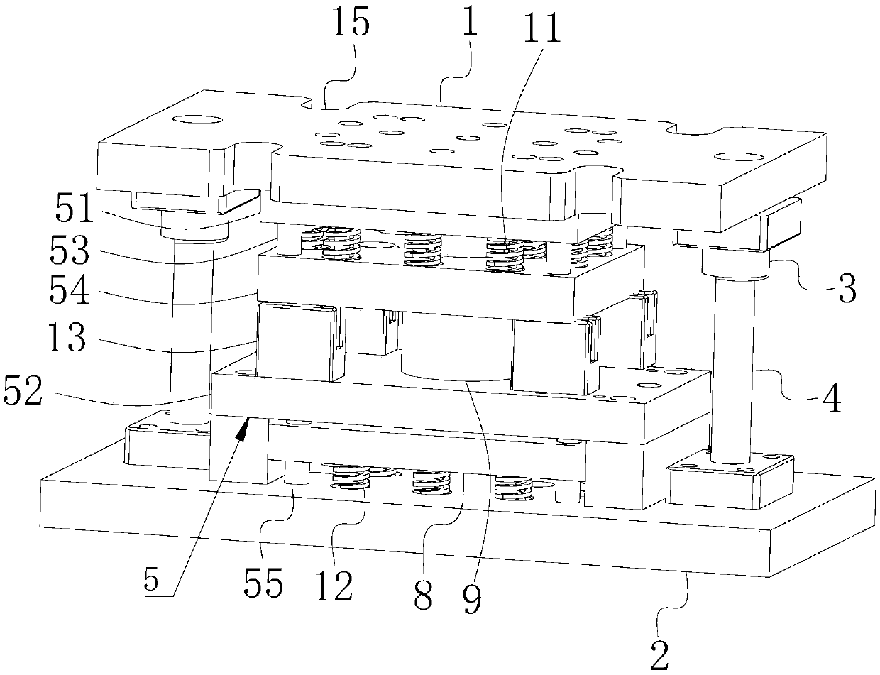
[0034] Embodiment: a kind of mold that is used for pipe fitting flaring, as figure 1 As shown, it includes an upper formwork 1 and a lower formwork 2 that can be close to each other. The upper formwork 1 is symmetrically provided with a guide sleeve 3 along the vertical direction, and a first guide post 4 is slidably connected in the guide sleeve 3. The templates 2 are connected through the first guide pillars 4 . The upper template (1) is evenly distributed around the entire upper template 1 along the axial direction of the stamping head 6, and the number is not less than four. Place the sling for the crane to facilitate the installation and transportation of the mold. A mold body 5 for forming is provided between the upper template 1 and the lower template 2. The mold body 5 includes a punch 51 and a die 52 that are matched with each other. The punch 51 is fixed on the upper template 1, and the die 52 is fixed on the lower die. Template 2 on.

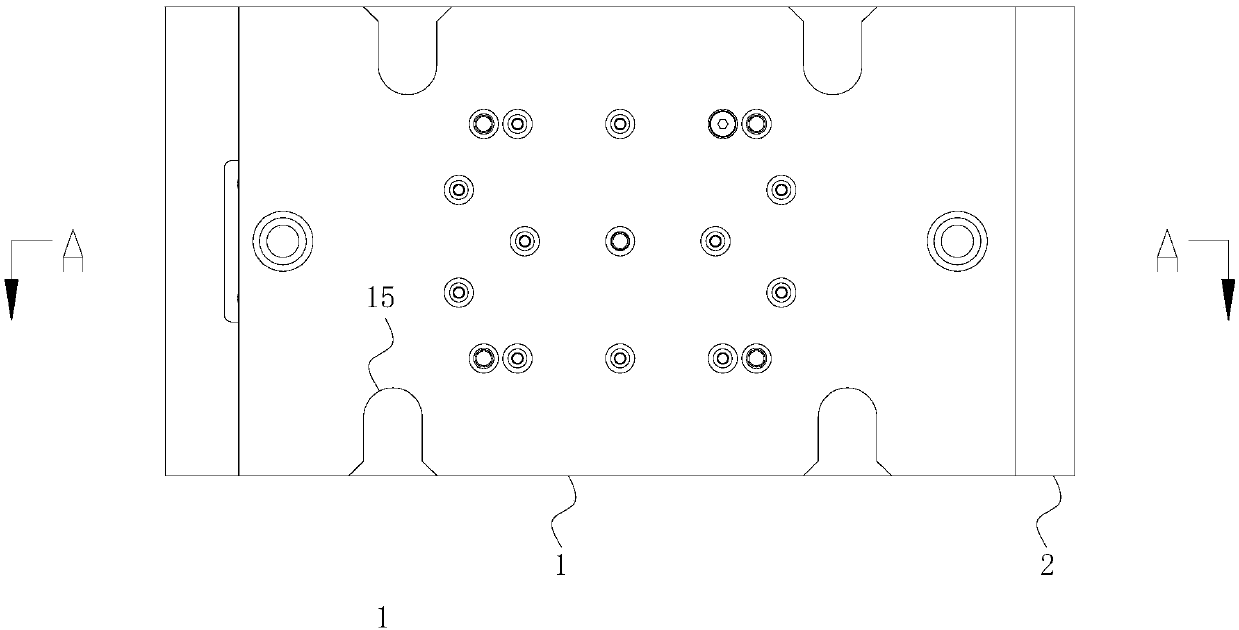
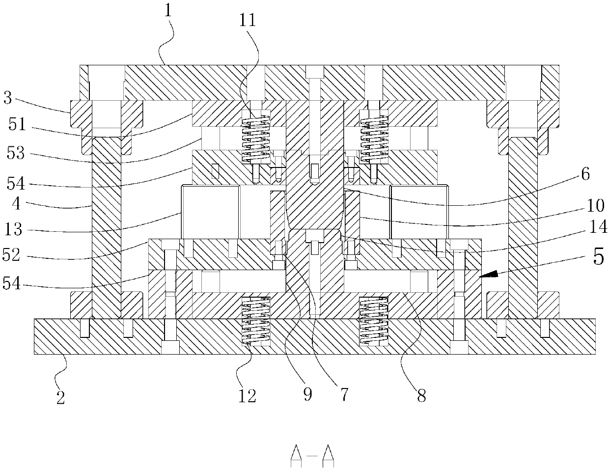
[0035] Such as figure 2 ...


PUM


Abstract

The invention discloses a die for flaring of a pipe fitting, relates to the technical field of dies, and solves the problems that a common pipe fitting is easily clamped with a stamping head, the clamped pipe fitting needs to consume a lot of time and energy of the workers during demoulding, and the machining efficiency of an enterprise can be dramatically reduced due to the large-batch to-be-machined pipe fitting. According to the technical scheme, a die body is arranged between an upper template and a lower template, the die body includes a convex die and a concave die, a stamping head is fixedly arranged on the convex die, a stripping plate in elastic connection with the convex die is in sliding connection between the convex die and the concave die, a machining through hole is formed inthe position, in the axial direction of the stamping head, of the concave die, a third guiding column is arranged between the concave die and the lower template, the outer wall of the third guiding column is in sliding connection with an ejecting plate, a die core is arranged on the ejecting plate, the die core is in sliding connection within the machining through hole. The purposes that by achieving the automatic demoulding of the pipe fitting, the efficiency of the flaring machining of the large-batch pipe fitting can be conveniently improved, and the flaring yield of the pipe fitting can be further improved are achieved.

Description

technical field [0001] The invention relates to the technical field of moulds, in particular to a mold used for flaring pipe fittings. Background technique [0002] As a channel for conveying media, pipes are widely used in petrochemical, instrumentation, aerospace, chemical, electric power, cement, metallurgy and other industries, and play an irreplaceable role in media transportation, power threading, machine tools, home appliances and other fields. However, when the open ends of the pipes are fixedly connected, the pipes without flares need to be connected with joints, and the pipes with flares can be directly installed without additional joints, which saves the installation cost of the pipes. [0003] Such as Figure 4 As shown, in the flaring processing of straight-through pipe fittings, because of the simple structure of this type of pipe fittings, workers often use the stamping head of the stamping equipment to directly squeeze the end of the pipe fittings, and then c...

Claims


Application Information

Patent Timeline
IPC IPC(8): B21D41/02B21D37/10B21D45/02
CPCB21D41/02B21D37/10B21D45/02
Inventor 伍朝砖
Owner 佛山市景和汽配有限公司
Why Eureka
Try Eureka