Fixing and cutting device for bridge frames

A technology of cutting device and bridge, which is applied in the direction of sawing machine device, metal sawing equipment, metal processing equipment, etc. It can solve the problems of affecting cutting effect and installation effect, uneven cutting surface of manual cutting, affecting the aesthetics of the process, etc., and achieves improvement. Cutting effect, convenient cutting, preventing left and right shaking effect

Inactive Publication Date: 2019-04-16
安徽祥君电气有限公司
1 Cites 2 Cited by

AI-Extracted Technical Summary

Problems solved by technology

[0006] Aiming at the deficiencies of the prior art, the present invention provides a fixed cutting device for the bridge, which overcomes the deficiencies of the prior art, has a reasonable design, and a compact structure, and solves the problem that the existing manual cutting of the bridge has an uneven cutting surface and affects the process. At the same time, it...

Method used

In the present embodiment, as shown in Figure 4, in order to improve the cutting effect, the cutting saw blade 15 includes a turntable 151, the side wall of the turntable 151 is connected with a plurality of connection blocks 152, and a plurality of connections The block 152 is connected with arc blades 153, and the rotating disk 151 is driven by the reversing motor 8 to rotate, so that a plurality of arc blades 153 begin to cut the bridge body 6, making the cutting saw blade 15 sharper and improving the cutting effect.
In the present embodiment, as shown in Figure 4, ...

Abstract

The invention relates to the technical field of fixing and cutting equipment for bridge frames, and provides a fixing and cutting device for the bridge frames. The device comprises a worktable, multiple support legs connected to the lower end of the worktable, two symmetric support plates connected to the upper end of the worktable, the same top plate connected to the upper ends of the two supportplates, a slide plate connected to the upper end of the worktable, and bridge frame main bodies butting against the upper end of the slide plate; and two end side walls of the slide plate both butt against fixing devices. The device overcomes the defects in the prior art, is reasonable in design and compact in structure, solves the problems of influence on the process beauty by uneven cutting surfaces due to traditional manual cutting of the bridge frames and influence on the cutting effect and the mounting effect due to no use of the fixing devices, adopts an automatic mechanical cutting method to achieve smooth incisions, meanwhile, adopts the fixing devices capable of sliding to automatically cut the bridge frames by operators only through shifting of the bridge frames, and improves the working efficiency.

Application Domain

Technology Topic

Image

  • Fixing and cutting device for bridge frames
  • Fixing and cutting device for bridge frames
  • Fixing and cutting device for bridge frames

Examples

  • Experimental program(1)

Example Embodiment

[0031] In order to make the objectives, technical solutions, and advantages of the embodiments of the present invention clearer, the technical solutions in the embodiments of the present invention will be described clearly and completely in conjunction with the accompanying drawings in the embodiments of the present invention. Obviously, the described embodiments It is a part of the embodiments of the present invention, not all the embodiments. Based on the embodiments of the present invention, all other embodiments obtained by those of ordinary skill in the art without creative work shall fall within the protection scope of the present invention.
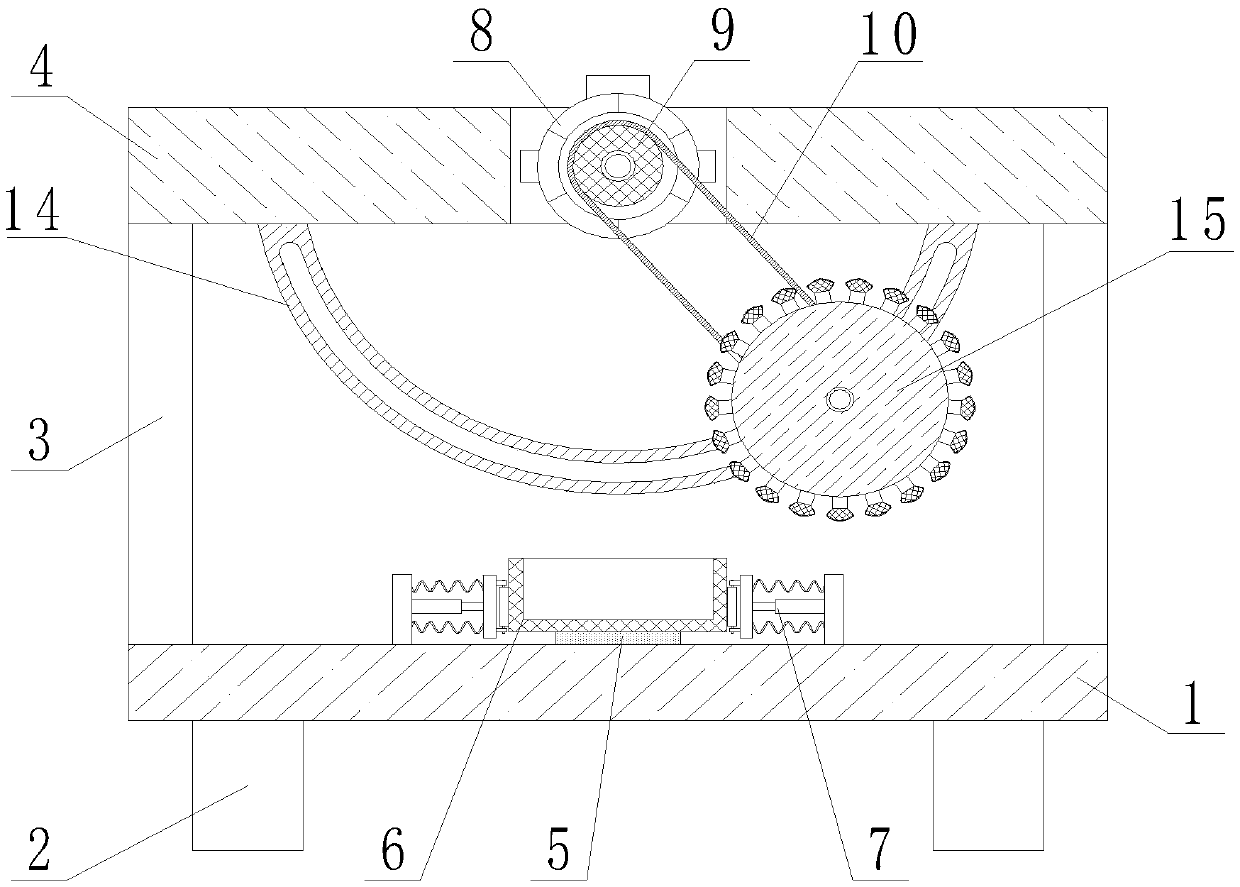
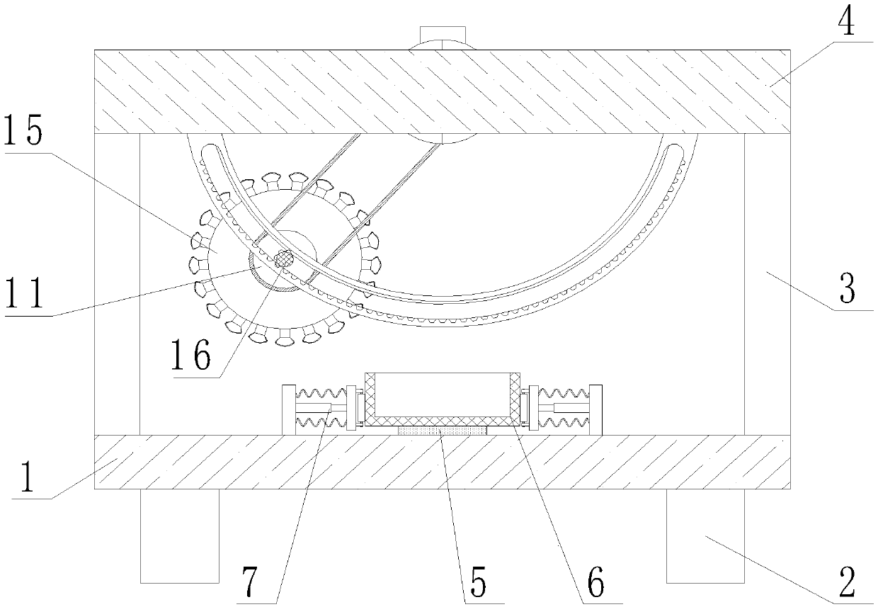
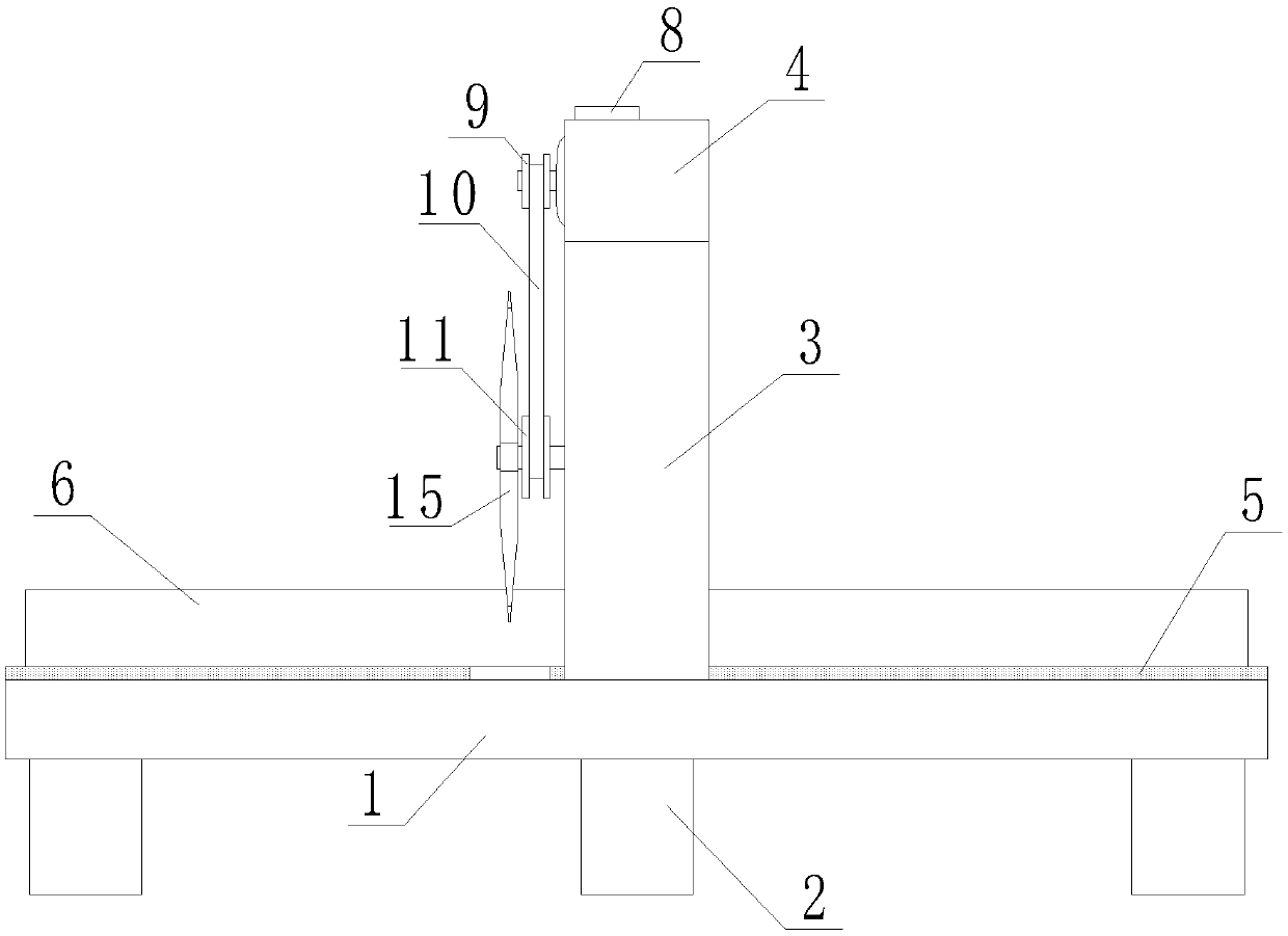
[0032] Reference attached Figure 1-6 , A fixed cutting device for bridge frame, comprising a workbench 1, a plurality of supporting legs connected to the lower end of the workbench 1, two symmetrical support plates 3 connected to the upper end of the workbench 1, and two support plates 3 The same top plate 4 at the upper end, a sliding plate 5 connected to the upper end of the worktable 1, and a bridge body 6 that abuts against the upper end of the sliding plate 5, and the two ends of the sliding plate 5 both abut against the fixing device 7, the fixing The device 7 includes a plurality of parallel rotating rollers 75, the rotating rollers 75 abut the bridge body 6, the top plate 4 is provided with a rectangular groove, and a forward and reverse motor 8 is connected in the rectangular groove. A first pulley 9 is connected to the rotating shaft of the motor 8, a second pulley 11 is connected to the first pulley 9 through a belt 10, a rotating shaft 12 is inserted into the center of the second pulley 11, and the rotation A sliding block 13 is movably sleeved on the shaft 12. The sliding block 13 is slidably connected to the inner side wall of the first arc-shaped sliding frame 14. The sliding block 13 has a cylindrical shape and acts as a limiter to make the rotating shaft 12 move along the Moving along the first arc-shaped sliding frame 14, the first arc-shaped sliding frame 14 is fixedly connected to the lower end of the top plate 4, one end of the rotating shaft 12 is fixedly connected with a cutting saw blade 15, and the other end of the rotating shaft 12 The missing gear 16 is sleeved, and the teeth of the missing gear 16 mesh with the tooth grooves opened on the inner wall of the second arc-shaped sliding frame. By reducing the teeth on the missing gear 16, the moving speed can be reduced, and the cutting effect can be improved. The second arc-shaped sliding frame is fixedly connected with the first arc-shaped sliding frame 14. When working, the bridge body 6 is placed on the sliding plate 5. At this time, the bridge body 6 is fixed by the fixing device 7 to start the forward and reverse motor 8 , The forward and reverse motor 8 drives the first pulley 9 to rotate, the first pulley 9 drives the second pulley 11 to rotate through the belt 10, and the second pulley 11 drives the rotating shaft 12 to rotate, thereby making the cutting saw blade 15 and the missing gear 16 rotates at the same time, the cutting saw blade 15 rotates to cut the bridge body 6, while the missing gear 16 rotates and engages the tooth groove on the inner wall of the second arc-shaped sliding frame, driving the rotating shaft 12 to move, as the forward and reverse motor 8 is positive The reverse rotation causes the cutting saw blade 15 to cut back and forth. At this time, the operator can smoothly cut the bridge body 6 by continuously pushing the bridge body 6, which improves the degree of mechanization, reduces labor, and improves the cutting effect.
[0033] In this embodiment, such as Image 6 As shown, in order to improve the fixing effect while ensuring that the bridge body 6 can slide, the fixing device 7 further includes a fixing plate 71. An end of the fixing plate 71 close to the bridge body 6 is connected with an electric telescopic rod 72. The other end is connected with a resisting plate 73, the electric telescopic rod 72 and the resisting plate 73 are connected to each other by a plurality of compression springs 74, the end of the resisting plate 73 close to the bridge body 6 is connected with a plurality of rollers 75 through a bracket, and the start The electric telescopic rod 72, the electric telescopic rod 72 drives the roller 75 to interfere with the bridge body 6, and the multiple rollers 75 against the bridge body 6 can ensure the fixing of the bridge body 6 and prevent the bridge body 6 from shaking left and right. At the same time, the rotating design is adopted to facilitate the bridge The main body 6 can slide back and forth to facilitate cutting.
[0034] In this embodiment, a rubber pad is connected to the lower end of the supporting foot 2 to play a buffering role and reduce noise pollution caused by the operation of the device.
[0035] In this embodiment, such as Figure 4 As shown, in order to improve the cutting effect, the cutting saw blade 15 includes a turntable 151. A plurality of connecting blocks 152 are connected to the side wall of the turntable 151, and arc blades 153 are connected to the plurality of connecting blocks 152. The turntable 151 is driven to rotate by the forward and reverse motor 8, so that the multiple arc blades 153 start to cut the bridge body 6, so that the cutting saw blade 15 is sharper and the cutting effect is improved.
[0036] In this embodiment, such as Figure 4 As shown, the number of the arc-shaped blades 153 is greater than or equal to 21, and the arc-shaped blades 153 are distributed equidistantly in a ring, and the arc-shaped blades 153 are distributed in a ring-shaped manner. The uniformity of cutting improves the fluency of cutting, which in turn improves the cutting effect.
[0037] In this embodiment, the distance between the cutting saw blade 15 and the working table 1 is greater than 5 cm, which prevents the cutting saw blade 15 from cutting to the working table 1 and thus damaging the working table 1.
[0038] In this embodiment, a rubber sleeve is sleeved on the roller 75, and the rubber sleeve is provided with anti-skid patterns to prevent the roller 75 from crushing the bridge body 6 and at the same time facilitate the bridge body 6 to slide on the roller 75.
[0039] In this embodiment, such as image 3 As shown, the sliding plate 5 is provided with a rectangular groove for cutting by the cutting saw blade 15 to prevent the cutting saw blade 15 from cutting the sliding plate 5, and at the same time, the distance between the cutting saw blade 15 and the worktable 1 is ensured.
[0040] The electrical components appearing in this article are all connected to an external main controller and 220 volt mains power, and the main controller can be a computer and other conventional known equipment that controls.
[0041] It should be noted that in this article, relational terms such as first and second are only used to distinguish one entity or operation from another entity or operation, and do not necessarily require or imply one of these entities or operations. There is any such actual relationship or order between. Moreover, the terms "include", "include" or any other variants thereof are intended to cover non-exclusive inclusion, so that a process, method, article or device including a series of elements not only includes those elements, but also includes those that are not explicitly listed Other elements of, or also include elements inherent to this process, method, article or equipment. If there are no more restrictions, the element defined by the sentence "including a..." does not exclude the existence of other same elements in the process, method, article, or equipment including the element.
[0042] The above embodiments are only used to illustrate the technical solutions of the present invention, but not to limit them; although the present invention has been described in detail with reference to the foregoing embodiments, those of ordinary skill in the art should understand that: The recorded technical solutions are modified, or some of the technical features are equivalently replaced; these modifications or replacements do not cause the essence of the corresponding technical solutions to deviate from the spirit and scope of the technical solutions of the embodiments of the present invention.

PUM

no PUM

Description & Claims & Application Information

We can also present the details of the Description, Claims and Application information to help users get a comprehensive understanding of the technical details of the patent, such as background art, summary of invention, brief description of drawings, description of embodiments, and other original content. On the other hand, users can also determine the specific scope of protection of the technology through the list of claims; as well as understand the changes in the life cycle of the technology with the presentation of the patent timeline. Login to view more.

Similar technology patents

Classification and recommendation of technical efficacy words

  • High degree of mechanization
  • Improve cutting effect

Automatic racking device for drill rod

Owner:建湖县鸿达阀门管件有限公司

Paper towel cutting mechanism

ActiveCN105996880AImprove cutting effectDomestic applicationsPaper towel
Owner:杭州迅行物联网科技有限公司

Plant trimming apparatus and methods

ActiveUS20190124851A1Improve cutting effectEasy to disassembleBud removersMowersAngular rangeLanding zone
Owner:ETEROS TECH INC
Why Eureka
Try Eureka