Method for machining tool billet

A technology for processing knives and billets, applied in the field of tool processing, can solve the problems of high production cost, increase the cost of steel raw materials, increase production cost, etc. produced effect

Active Publication Date: 2019-04-16
DONGE LIYUAN MACHINERY KNIFE
View PDF5 Cites 1 Cited by
  • Summary
  • Abstract
  • Description
  • Claims
  • Application Information

AI Technical Summary

Problems solved by technology

[0005] (1) In the process of tool processing, the raw materials are cut into blanks one by one for processing. Each blank is an independent product to be processed. The processing is cumbersome, the efficiency is difficult to improve, and the production cost is high.
[0006] (2) There are many tool processing steps, and the stability and uniformity of the tool performance are inconsistent during the processing process. Different operators and different equipment will have differences. At the same time, there will be a reject rate during the processing process. The main factors that affect the quality are the welding process, especially for tools with larger cross-sections. Due to the amount of solder used during the welding process, the quality of the solder itself, the stability of the substrate and high-speed steel bars during the welding process, etc. The result of welding is affected by
[0007] (3) The post-welding treatment process is performed on the welded blanks one by one. There are also problems suc

Method used


Image

  • Method for machining tool billet
  • Method for machining tool billet
  • Method for machining tool billet

Examples


Embodiment Construction

[0045] The following examples further illustrate the present invention.

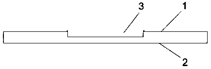
[0046] Combine Figure 1-Figure 3 It can be seen that in the prior art substrate, after the substrate and the high-speed steel bar 6 are welded, it is necessary to plan the blade first and then cut, or cut first and then plan the blade. In order to improve efficiency, the method of planing the blade and then cutting is often adopted. During the planing process, more parts need to be removed. One is the waste of steel, a large amount of metal waste is produced, and production costs such as labor, machinery and electricity are increased.

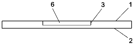
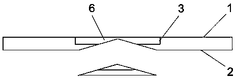
[0047] Combine Figure 4-Figure 7 It can be seen that the method for processing tool blanks of the present invention includes the following steps:

[0048] (1) Production of the substrate. The upper surface 1 of the substrate is provided with an inlay groove 3, which fixes the high-speed steel bar 6; the depth of the inlay groove 3 is equal to the thickness of the high-speed s...


PUM


Abstract

The invention discloses a method for machining a tool billet. The method comprises the following steps that (1) a substrate is produced, an inlay groove is formed in the upper surface of the substrate, and a high speed steel bar is arranged in the inlay groove, the depth of the inlay groove is equal to the thickness of the high speed steel bar, and a cutting planer groove is formed in the lower surface of the substrate and formed under the inlay groove; (2) the high speed steel bar is nested into the inlay groove in the main body of the substrate to be fixed; (3) the main body of the substrateinlaid with the high speed steel bar is welded, so that the high speed steel bar is firmly connected with the main body of the substrate; and (4) cutting is conducted, the welded substrate main bodyand the high speed steel bar are cut into two parts in the length direction of the cutting planer groove. The method can further save the raw material cost of a machining tool and improve the utilization rate of the material, meanwhile, can further reduce the cutting or planing workload of the follow-up work, further reduce the production cost, improve the production efficiency, and have outstanding economic and social benefits.

Description

Technical field [0001] The present invention relates to tool machining, specifically a method for machining tool blanks. Background technique [0002] In the process of tool processing, the cutting edge has high hardness. Generally, the tool body is made of a base plate made of steel material, and high-speed steel bars are laid and welded on the grooved platform. [0003] The specific process of the above-mentioned tool processing includes the following steps: blanking-punching-billet straighter-grooving table-cleaning-welding-tempering (tempering as many times as necessary, generally 2-3 times)-straightening-grinding order Face-milling single side-fine grinding width-fine grinding length-planer blade-straightening-fine grinding blade-cleaning, rust prevention, finished product packaging. [0004] The above processing process has the following technical problems: [0005] (1) In the process of tool processing, the raw materials are cut one by one into blanks for processing. Each blan...

Claims


Application Information

Patent Timeline
IPC IPC(8): B23P15/28
CPCB23P15/28
Inventor 许纪刚
Owner DONGE LIYUAN MACHINERY KNIFE
Why Eureka
Try Eureka