cryogenic storage device

A storage device, low temperature technology, applied in unloading devices, household refrigeration devices, thermal insulation containers, etc., can solve problems such as frostbite, large liquid nitrogen loss, and many operations, saving volume, reducing liquid nitrogen loss, and effective Good results

Active Publication Date: 2020-01-21
郭福军
View PDF5 Cites 0 Cited by
  • Summary
  • Abstract
  • Description
  • Claims
  • Application Information

AI Technical Summary

Problems solved by technology

This method is time-consuming due to many manual sampling operations, which is not only prone to frostbite, but also causes a large loss of liquid nitrogen
There is also a liquid nitrogen tank that is driven by an external motor to reduce manual sampling operations, but this method produces additional liquid nitrogen loss due to the introduction of an external drive to connect the inside and outside of the liquid nitrogen tank

Method used


Image

  • cryogenic storage device
  • cryogenic storage device
  • cryogenic storage device

Examples


Embodiment Construction

[0013] In order to make the purpose, technical solutions and advantages of the present invention clearer, the technical solutions in the embodiments of the present invention will be clearly and completely described below in conjunction with the accompanying drawings in the embodiments of the present invention. Obviously, the described embodiments are the Some, but not all, embodiments are invented. Based on the embodiments of the present invention, all other embodiments obtained by persons of ordinary skill in the art without creative efforts fall within the protection scope of the present invention.

[0014] In order to make the technical solution of the present invention more clear, the embodiments of the present invention will be described in detail below in conjunction with the accompanying drawings.

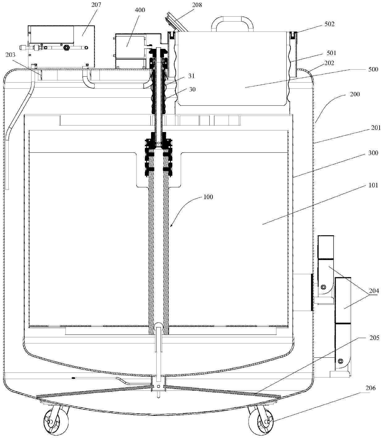
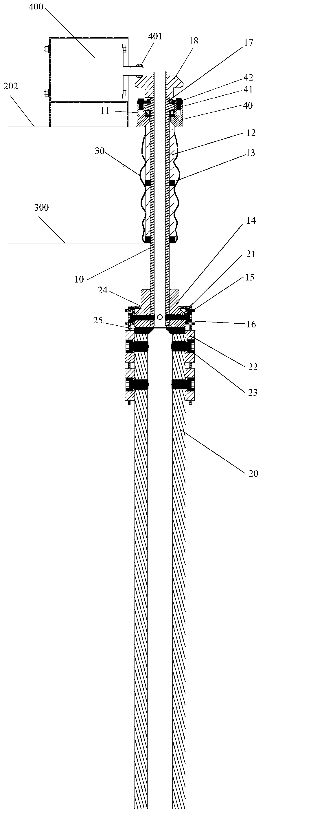
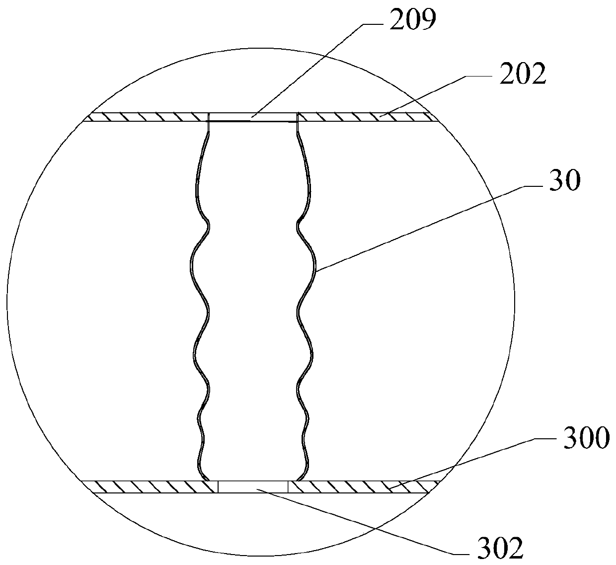
[0015] figure 1 It is a schematic structural diagram of a low-temperature storage device provided by an embodiment of the present invention, figure 2 for figure 1 The sc...


PUM


Abstract

The invention discloses a low-temperature storage device. The low-temperature storage device comprises an outer tank, shaft assemblies, an inner container and a driving assembly, wherein the inner container is arranged in the outer tank, and the driving assembly is arranged outside the outer tank. The inn container is connected and fixed with the outer tank. The center of the top of the outer tankand the center of the top of the inner container are provided with shaft holes for the shaft assemblies to penetrate. The shaft hole in the top of the outer tank is connected with the shaft hole in the top of the inner container through a corrugated pipe. First heat insulation assemblies for blocking airflow convection are arranged between the corrugated pipe and the shaft assemblies. The shaft assembly located inside the inner container is provided with an inner rotator for placing biological samples in different zones, and the shaft assembly located outside the outer tank is connected withthe driving assembly. Corresponding eccentric positions of the top of the outer tank and the top of the inner container are provided with object taking holes serving as biological sample taking and placing channels, and an openable heat preservation cover is arranged between the two object taking holes. The low-temperature storage device effectively reduces the loss of liquid nitrogen and has a better effect of storing the biological samples.

Description

technical field [0001] The invention relates to the technical field of low-temperature storage, in particular to a low-temperature storage device. Background technique [0002] In the field of biomedicine, low-temperature storage in a liquid nitrogen environment can enable long-term active preservation of biological tissues such as blood, stem cells, and vaccines. Biological samples are usually placed in liquid nitrogen tanks in partitions. When in use, the operator opens the extraction hole Take out the biological sample to be extracted from the liquid nitrogen tank. [0003] In the use of existing liquid nitrogen tanks, most operators need to reach into the liquid nitrogen tank through the extraction hole to move the sample placement partition, and take out the sample when the sample to be extracted is rotated to the bottom of the extraction hole. Due to many manual sampling operations and time-consuming, this method is not only prone to frostbite, but also causes a large...

Claims


Application Information

Patent Timeline
Patent Type & Authority Patents(China)
IPC IPC(8): B65D81/38B65D81/18B65D25/52B65D25/24
CPCB65D25/24B65D25/52B65D81/18B65D81/38
Inventor 郭福军
Owner 郭福军
Why Eureka
Try Eureka