
PCB automatic collecting and placing machine and working method thereof

A PCB board and board machine technology, applied in the direction of conveyor objects, loading/unloading, furnaces, etc., can solve the problems of low automation, low adaptability, easy short-circuit damage of PCB boards, etc., to achieve efficient work and ensure cleanliness , the effect of improving efficiency

Active Publication Date: 2019-04-16
领跃电子科技(珠海)有限公司
View PDF11 Cites 7 Cited by
  • Summary
  • Abstract
  • Description
  • Claims
  • Application Information

AI Technical Summary

Problems solved by technology

[0005] The purpose of the present invention is to solve the problem that the existing retractable board machine for PCB boards is low in automation, time-consuming and labor-intensive to use, and the efficiency of retracting and retracting PCB boards is slow, and the problem of retracting and retracting PCB boards is low. The storage capacity is low, and when retracting the PCB board, the retractable board machine cannot dry and clean the board body, resulting in the long-term storage of the PCB board in the storage frame, which is prone to moisture and rust, and the PCB board is easy to use when in use. The short circuit is damaged, and the retractable board machine can only retract and retract PCB boards with the same width and thickness, and the adaptability is relatively low. Therefore, an automatic PCB board retractable board machine and its working method are proposed

Method used


Image

  • PCB automatic collecting and placing machine and working method thereof
  • PCB automatic collecting and placing machine and working method thereof
  • PCB automatic collecting and placing machine and working method thereof

Examples


Embodiment Construction

[0049] The technical solutions of the present invention will be clearly and completely described below in conjunction with the embodiments. Apparently, the described embodiments are only some of the embodiments of the present invention, not all of them. Based on the embodiments of the present invention, all other embodiments obtained by persons of ordinary skill in the art without creative efforts fall within the protection scope of the present invention.

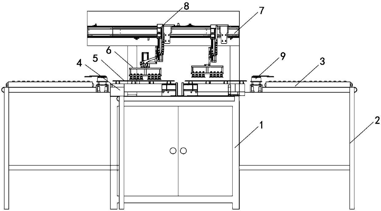
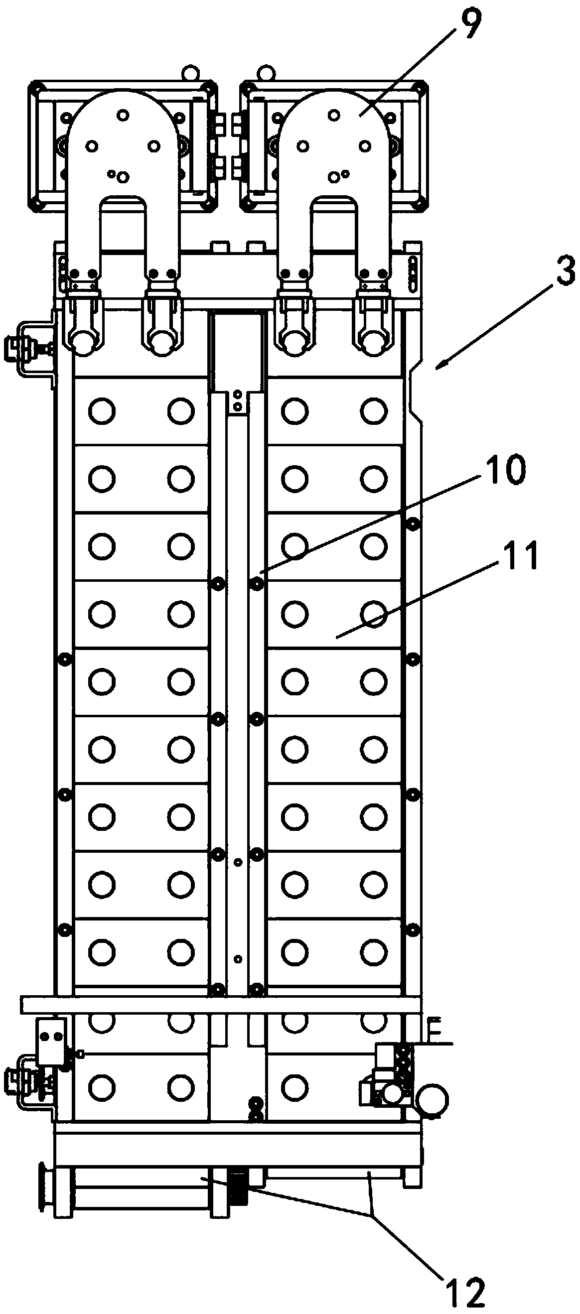
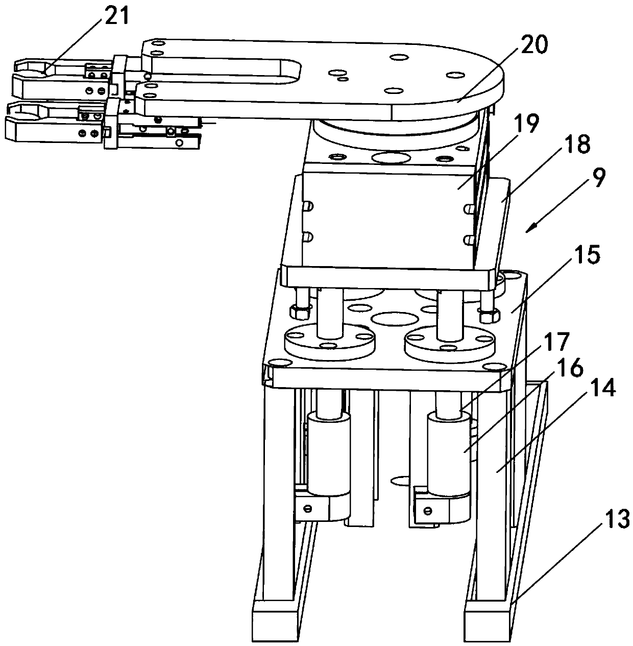
[0050] see Figure 1-12 As shown, a PCB board automatic retractable board machine includes a mounting base 1, a support frame 2, a rolling tray 3, a retractable cabinet 4, a turntable 5, a blast frame 6, a horizontal rail rod 7, a vertical rail rod 8 and Grab and place seat 9, support frame 2 is arranged at both ends of mounting seat 1, and rolling tray 3 is horizontally arranged above two support frames 2, and both ends of mounting seat 1 are provided with retractable cabinet 4, two retractable The top of the cabinet 4 is...


PUM


Abstract

The invention discloses a PCB automatic collecting and placing machine and a working method thereof. The machine comprises a mounting seat, supporting frames, rolling and conveying discs, a collectingand placing cabinet, a rotary disc, an air blowing frame, a transverse rail rod, a longitudinal rail rod and a grabbing and placing seat, wherein the supporting frames are arranged at the two ends ofthe mounting seat, and the rolling and conveying discs are horizontally arranged above the two supporting frames. The machine has the beneficial effects that a plurality of air blowing cylinders on the air blowing frame synchronously blow hot air to a board body, so that the drying performance of a PCB is guaranteed when the PCB is collected and placed, dust and impurities on the PCB are blown away, so that the tidiness of the PCB when the PCB is collected and placed is guaranteed, then a hydraulic pump II on the collecting and placing cabinet drives a rotary disc to move downwards into a receiving bucket through a hydraulic rod, after a mechanical arm clamps the PCB through clamping jaws, the hydraulic rod drives the rotary disc to rise, a third rolling wheel drives the mechanical arm toextend out of a movable groove, and place the PCB into a loading groove of a loading frame, so that the automatic collecting and placing of the PCB can be completed, the operation of the collecting and placing machine is more time-saving and labor-saving, and the work is more efficient.

Description

technical field [0001] The invention relates to a retractable trigger, in particular to an automatic PCB retractable trigger and a working method thereof, belonging to the technical field of retractable trigger applications. Background technique [0002] PCB board, also known as printed circuit board, is the provider of electrical connection for electronic components. The main advantage of using PCB boards is to greatly reduce the errors of wiring and assembly, and improve the automation level and production labor rate. According to the number of layers of circuit boards, it can be divided into single-sided boards, double-sided boards, four-layer boards, six-layer boards and other multi-layer circuit boards. [0003] During the production and processing of PCB boards, a retractable board machine is required to store the PCB boards in the storage box, which is convenient for the staff to organize and package the PCB boards. [0004] There are still many deficiencies in the ...

Claims


Application Information

Patent Timeline
Patent Type & Authority Applications(China)
IPC IPC(8): B65G47/90B65G49/06B65G69/20
CPCB65G47/902B65G49/061B65G49/068B65G69/20
Inventor 伍超张鸿恺陈杰王菲露徐勇王丽蓉
Owner 领跃电子科技(珠海)有限公司
Learn More