Sound-absorbing room building floor structure

A sound-absorbing room and sound-absorbing panel technology, which is applied in building structure, construction, layered products, etc., can solve the problems of difficult volatilization and removal of water vapor and reduced sound-absorbing effect, achieve good sound-absorbing effect, avoid the reduction of sound-absorbing effect, and improve sound-absorbing effect of effect

Active Publication Date: 2019-04-16
WENZHOU FENGCHENG CONSTR CO LTD
View PDF10 Cites 0 Cited by
  • Summary
  • Abstract
  • Description
  • Claims
  • Application Information

AI Technical Summary

Problems solved by technology

Its shortcoming is that after the existing sound-absorbing panel 4 is infiltrated by the liquid seeping down above the surface layer 5 or the water vapor rising below the lower keel 1, due to the limitation of the floor structure, the water vapor in the sound-absorbing panel 4 is difficult to volatilize and remove, resulting in Long-term reduction in sound absorption

Method used


Image

  • Sound-absorbing room building floor structure
  • Sound-absorbing room building floor structure
  • Sound-absorbing room building floor structure

Examples


Embodiment 1

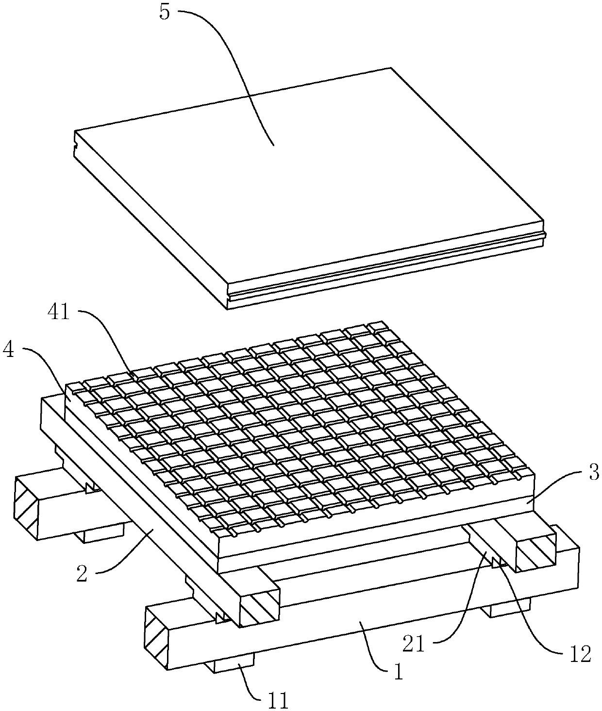
[0060] as attached figure 1 As shown, a sound-absorbing room building floor structure includes a lower keel 1, an upper keel 2, a lining board 3, a sound-absorbing layer 4b and a surface board 5. The lower keel 1 and the upper keel 2 are elongated, and the number of the two depends on the size of the indoor laying area. In the figure, the lower keel 1 and the upper keel 2 are interlaced to form a frame unit. The lower keels 1 are distributed at equal intervals, and at the same time, a plurality of pads 11 are arranged at intervals on the bottom surface of each lower keel 1 . The shape of the spacer 11 is determined according to the actual situation, and the spacer 11 is a cuboid shape equal to the width of the lower keel 1 here. Simultaneously, the upper surface of the lower keel 1 is equidistantly provided with sunken caulking grooves 12 along its length direction. The shape of the caulking grooves 12 can be determined according to the actual situation.

[0061] The upper ...

Embodiment 2

[0095] A floor structure for a sound-absorbing room, based on Embodiment 1A, the difference is that the sound-absorbing panel only includes a sound-absorbing layer, the upper surface of the sound-absorbing layer is in contact with the lower surface of the surface layer, and the lower surface of the sound-absorbing layer is in contact with the lower surface of the surface layer. The lower bottom surface of the liner is attached to each other.

Embodiment 3

[0097] A sound-absorbing room building floor structure, based on the basis of Example 1A, the difference is that the shell powder is soaked in the eluate at low temperature and then filtered, and then the water with the same quality as the shell powder and ethanol with the same quality as the shell powder are used successively Wash and dry in an oven at 350°C.


PUM

PropertyMeasurementUnit
particle diameteraaaaaaaaaa
thicknessaaaaaaaaaa

Abstract

The invention relates to an indoor building structure of a house, and discloses a sound-absorbing room building floor structure. The problems that an existing sound-absorbing room building floor structure is limited by a floor structure, water vapors are difficult to volatilize after the sound-absorbing layer is wet, and the sound absorbing effect is reduced for a long time are solved, according to the technical scheme, the structure comprises a lower keel and an upper keel which are horizontally and vertically erected and a lining, a sound absorbing panel and a topping board which are superposed on the upper keel from bottom to top, and the structure is characterized in that the sound absorbing panel further comprises a sound absorbing layer, the sound absorbing layer is prepared from, bymass, 90-125 parts of an epoxy resin and 140 parts of sound absorbing powder, the sound absorbing powder is shell powder dried after low temperature soaking of an eluate, the eluate is a 4 wt% urea / 8wt% aqueous solution, a soaking temperature is 15-12 DEG C, a soaking time is 10-15 min, the mass ratio of the eluate to the shell powder to be soaked is 10:3, the shell powder has a particle size of80-100 nm, and the sound-absorbing panel with good pressure bearing strength and moisture-proof performance is installed to avoid the reduction of the sound absorption effect on a room building floorin a wet environment.

Description

technical field [0001] The invention relates to a house indoor building structure, in particular to a sound-absorbing room building floor structure. Background technique [0002] With the development of modern housing construction and the improvement of living needs, the current sound-absorbing room building floor structure is no longer just a direct floor panel laid and fixed on the indoor ground. For the increasing requirements, the building floor structure has made corresponding Improve. [0003] as attached Figure 4 As shown, the existing house floor structure includes a lower keel 1 , an upper keel 2 , a lining board 3 , a sound-absorbing board 4 and a surface board 5 . The lower keel 1 and the upper keel 2 are elongated, and the number of the two is multiple and depends on the size of the indoor laying area. The lower keels 1 are distributed at equal intervals, and at the same time, a plurality of pads 11 are arranged at intervals on the bottom surface of each lower...

Claims


Application Information

Patent Timeline
Patent Type & Authority Applications(China)
IPC IPC(8): E04F15/02E04F15/20C08L63/00C08K9/04C08K3/26C08K5/54C08K3/22B32B9/00B32B9/04B32B3/30
CPCB32B3/30B32B9/00B32B9/04C08K3/22C08K3/26C08K5/54C08K9/04C08K2003/2286C08K2003/265C08K2201/011E04F15/02044E04F15/20E04F2290/041C08L63/00
Inventor 陈孝义陈仁义
Owner WENZHOU FENGCHENG CONSTR CO LTD
Why Eureka
Try Eureka