
Water plugging and acidification joint operation method for high-water-cut oil well in low-permeability oil field

A technology for water plugging and joint operation of oil wells, which is applied to earth-moving drilling, wellbore/well components, and production fluids, etc. It can solve problems such as affecting oilfield production efficiency, rising water content of oil wells, and water-flooded production stoppage, and achieve the effect of improving measures. And the effect of efficiency, improving efficiency and saving cost

Inactive Publication Date: 2019-04-16
杨凌单色生物科技有限公司
View PDF7 Cites 3 Cited by
  • Summary
  • Abstract
  • Description
  • Claims
  • Application Information

AI Technical Summary

Problems solved by technology

However, as the production and development of the oilfield enters the middle and late stages, the energy of the formation is insufficient, and the oilfield adopts water injection and other development methods, which leads to the increase of the water content of the oil well and even the shutdown of production due to water flooding; Formation is clogged, leading to a decline in production. Measures such as acidizing and fracturing are needed to improve the seepage capacity of the formation to meet production needs, especially in low-permeability oil fields. In later development, in order to ensure production needs, oil and gas wells need to be acidified , fracturing and other production stimulation measures
However, for oilfields using water injection development method, and oil wells with edge, bottom water or adjacent water injection wells in the reservoir, after acidizing measures, it is easy to lead to better communication of the water-bearing area, resulting in an increase in the water cut of the oil well, and in severe cases It leads to problems such as water flooding, water channeling and even scrapping of oil wells, which seriously affects the production efficiency of the oil field, but the existing acidizing technology cannot avoid this problem well

Method used


Image

  • Water plugging and acidification joint operation method for high-water-cut oil well in low-permeability oil field
  • Water plugging and acidification joint operation method for high-water-cut oil well in low-permeability oil field

Examples


Embodiment 1

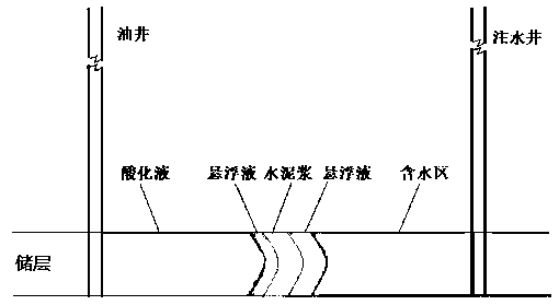
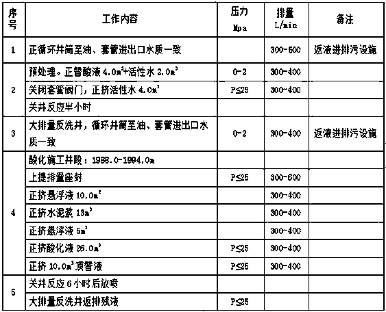
[0027] The combined operation method of water plugging and acidizing of high water content oil wells in low permeability oilfields, first inject a section of high viscosity suspension with a low displacement by a pump truck to push the water fluid in the formation to the rear; then use a cement truck to inject cement slurry into the formation , used to block the water channeling part; then, use a pump truck to inject a section of high-viscosity suspension into the formation to replace the cement slurry to the rear; finally, use a pump truck to pump acidizing liquid into the formation to implement acidification and blockage removal, among which, The initial setting time of cement slurry is more than 6 hours. Among them, the low displacement is 300-400L / min.

[0028] The high-viscosity suspension is composed of 3.5%~4.0% oligoaminosuccinic acid fatty acid ester salt, 0.4%~0.5% formic acid, 1.0%~2.0%KCl and 93.5%~95.1%H 2 O is mixed according to the above mass ratio; the viscosi...

Embodiment 2

[0033] A method for combined operation of water plugging and acidizing in high water-cut oil wells in low-permeability oilfields, comprising the following steps:

[0034] Step 1: Prepare before acidizing construction, prepare cement slurry, acidizing liquid and high-viscosity suspension;

[0035] Step 2: First use a pump truck to inject a high-viscosity suspension with a low displacement to push the water and other fluids in the formation to the rear; at the same time, avoid the acidizing liquid from damaging the cement plugging effect;

[0036] Step 3: Use a cement truck to inject cement slurry into the formation to block the water channeling part; wherein, the initial setting time of the cement slurry is greater than 6 hours;

[0037] Step 4: Use a pump truck to inject a section of high-viscosity suspension into the formation to replace the cement slurry to the rear;

[0038] Step 5: Use the pump truck to transfer and inject the acidizing fluid into the formation, and imple...

Embodiment 3

[0047] Basically the same as embodiment 2, the difference is:

[0048] The high-viscosity suspension is composed of 4.0% oligomeric aminosuccinic acid fatty acid ester salt, 0.5% formic acid, 2.0% KCl and 93.5%%H 2 O is mixed according to the above mass ratio; the viscosity of the high-viscosity suspension liquid at 25°C is greater than 100mPa.

[0049] The cement slurry is mixed with 70% G grade cement, 28% clear water and 2.0% retarder.

[0050] The acidizing solution is formed by mixing 15% hydrochloric acid, 3% fluoboric acid, 2% hydrofluoric acid, 2% corrosion inhibitor for acidification, 1% iron ion stabilizer, 1% clay stabilizer and 76% clear water.


PUM


Abstract

The invention relates to the technical field of oil and gas field production and development, in particular to a water plugging and acidification joint operation method for a high-water-cut oil well in a low-permeability oil field. The method is characterized by including the steps that firstly, a section of high-viscosity suspension is injected at a low displacement with a pump truck to push a water fluid in a stratum to the rear; then, cement slurry is injected into the stratum with a cement truck for plugging a water channeling part; then, a section of high-viscosity suspension is injectedinto the stratum with the pump truck to replace the cement slurry to the rear; finally, acidification liquid is pumped into the stratum with the pump truck to carry out acidification plugging removal, wherein the initial setting time of the cement slurry is longer than 6 hours. The method effectively solves the problems that as a crack is communicated with a water containing zone in acidification, an oil well is communicated with a water injection well or an oil layer is communicated with an edge or bottom water layer through the crack, and consequently the water cut of the oil well rises oreven the oil well floods.

Description

technical field [0001] The invention relates to the technical field of production and development of oil and gas fields, in particular to a method for combined operation of water shutoff and acidification of high water content oil wells in low permeability oil fields. Background technique [0002] Oil well acidizing technology, as an important stimulation measure to relieve clogging near the wellbore and improve formation permeability, has been widely used in the production and development of major oilfields and played an important role, especially in the development of carbonic acid reservoirs. application is more common. However, as the production and development of the oilfield enters the middle and late stages, the energy of the formation is insufficient, and the oilfield adopts water injection and other development methods, which leads to the increase of the water content of the oil well and even the shutdown of production due to water flooding; Formation is clogged, l...

Claims


Application Information

Patent Timeline
IPC IPC(8): E21B33/13E21B43/22
CPCE21B33/13E21B43/16
Inventor 肖良飞陈柯全刘畅
Owner 杨凌单色生物科技有限公司
Learn More