Oil-gas well slug flow combined type gas slug breaking device and method

A technology for oil and gas wells and slug flow, which is applied in the direction of production fluid, earthwork drilling, wellbore/well components, etc., and can solve the problems of large pressure drop and liquid phase accumulation in the bubble breaking device

Inactive Publication Date: 2019-04-16
SOUTHWEST PETROLEUM UNIV
View PDF9 Cites 7 Cited by
  • Summary
  • Abstract
  • Description
  • Claims
  • Application Information

AI Technical Summary

Problems solved by technology

[0005] The purpose of the present invention is to provide a combined gas slug crushing device for oil and gas well slug flow, aiming to solve the problems of large pressure drop and liquid phase accumulation in the existing oil and gas well slug flow bubble breaking device

Method used


Image

  • Oil-gas well slug flow combined type gas slug breaking device and method
  • Oil-gas well slug flow combined type gas slug breaking device and method
  • Oil-gas well slug flow combined type gas slug breaking device and method

Examples


Embodiment Construction

[0020] In order to make the object, technical solution and advantages of the present invention clearer, the present invention will be further described in detail below in conjunction with the accompanying drawings and embodiments. It should be understood that the specific embodiments described here are only used to explain the present invention, not to limit the present invention.

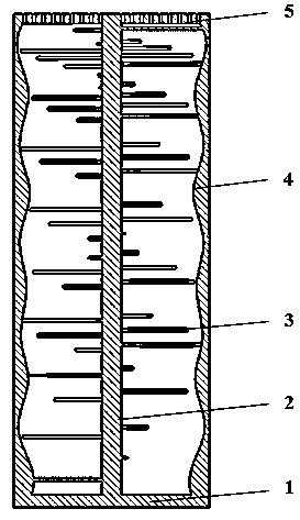
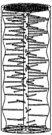
[0021] like Figure 1-4 As shown, among them, figure 1 It is the structural assembly drawing (sectional view) of the oil and gas well slug flow combined gas slug crushing device of the present invention; figure 2 It is the structural assembly drawing (perspective view) of the oil and gas well slug flow combined gas slug crushing device of the present invention; image 3 It is a top view of the external structure of the oil and gas well slug flow combined gas slug breaking device of the present invention; Figure 4 It is a bottom view of the external structure of the oil and gas well slug flow c...


PUM


Abstract

The invention provides an oil-gas well slug flow combined type gas slug breaking device and method, and relates to the field of slug flow bubble breaking. A bubble breaking device is composed of an entry cross-bar, a central column, vibratile metal wires, a corrugated tube wall and a perforated plate; the entry cross-bar supports the central column, and a slug is initially broken; the vibratile metal wires spirally rise along the central column and are arranged from thin to dense, and the problem that a fluid is stirred irregularly, and bubble braking is incomplete is solved; by means of the corrugated tube wall, turbulent fluctuation and fluid impact are improved, and a liquid film is dispersed into a gas phase; by means of the perforated plate, the bubbles are broken into small bubbles meeting the requirements; the residual liquid film on the tube wall flows out of a hole tangent to the liquid film to prevent liquid phase accumulation. Accordingly, by means of combined design, two kinds of bubble breaking methods are organically combined and improved, and the defect of the single method is overcome; the corrugated tube wall is adopted, the turbulence intensity is improved, gas-liquid distribution is improved, the pressure drop loss is reduced, the oil-gas well maintenance period is prolonged, and the oil-gas field development benefit is increased.

Description

technical field [0001] The invention relates to the field of bubble crushing in oil and gas well slug flow, in particular to a combined gas slug crushing device in front of an oil and gas well slug flow downhole gas-liquid separator. Background technique [0002] In the middle and later stages of oil and gas well production, as the formation pressure continues to drop, the bottom hole pressure decreases, and the pressure of the fluid rises along the wellbore decreases. The liquid ratio state maintains production for a long time. In order to stabilize production and increase efficiency, production units generally adopt artificial lifting measures such as rod pumps and electric submersible pumps in the wellbore to increase recovery, and at the same time equip downhole gas-liquid separators to reduce the impact of gas on lifting tools. In slug flow, due to the special structure of a section of gas and a section of liquid, the gas occupies the center of the wellbore in the form...

Claims


Application Information

Patent Timeline
Patent Type & Authority Applications(China)
IPC IPC(8): E21B43/12
CPCE21B43/12
Inventor 刘永辉王光彪谢川王朗吴朋勃李一丰黄远军
Owner SOUTHWEST PETROLEUM UNIV
Why Eureka
Try Eureka