
Deep shaft rock tunnel boring machine

A technology for roadheaders and deep shafts, applied in shaft equipment, well sinking, mining equipment, etc., can solve the problems of difficult automation, cumbersome construction, and high labor intensity.

Pending Publication Date: 2019-04-16
CHINA RAILWAY CONSTR HEAVY IND
View PDF22 Cites 6 Cited by
  • Summary
  • Abstract
  • Description
  • Claims
  • Application Information

AI Technical Summary

Problems solved by technology

However, this kind of equipment is difficult to automate, there are many processes, the construction is cumbersome, and the sinking efficiency is low, the labor intensity is high, and most importantly, the excavation depth is limited, so it is difficult to realize deep shaft construction.

Method used


Image

  • Deep shaft rock tunnel boring machine
  • Deep shaft rock tunnel boring machine
  • Deep shaft rock tunnel boring machine

Examples


Embodiment Construction

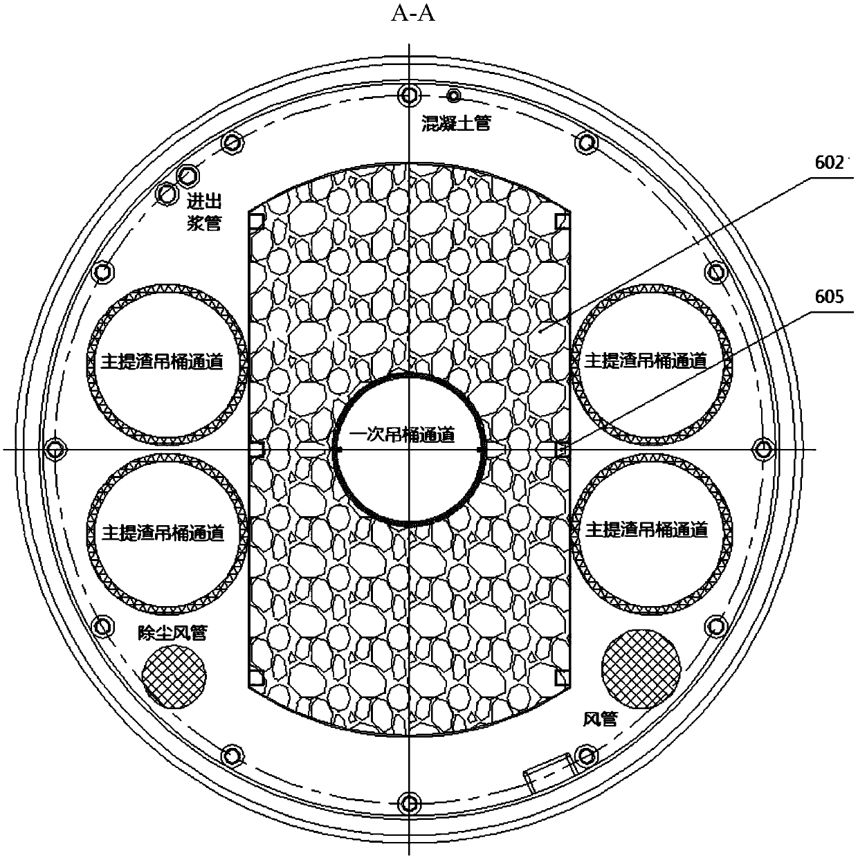
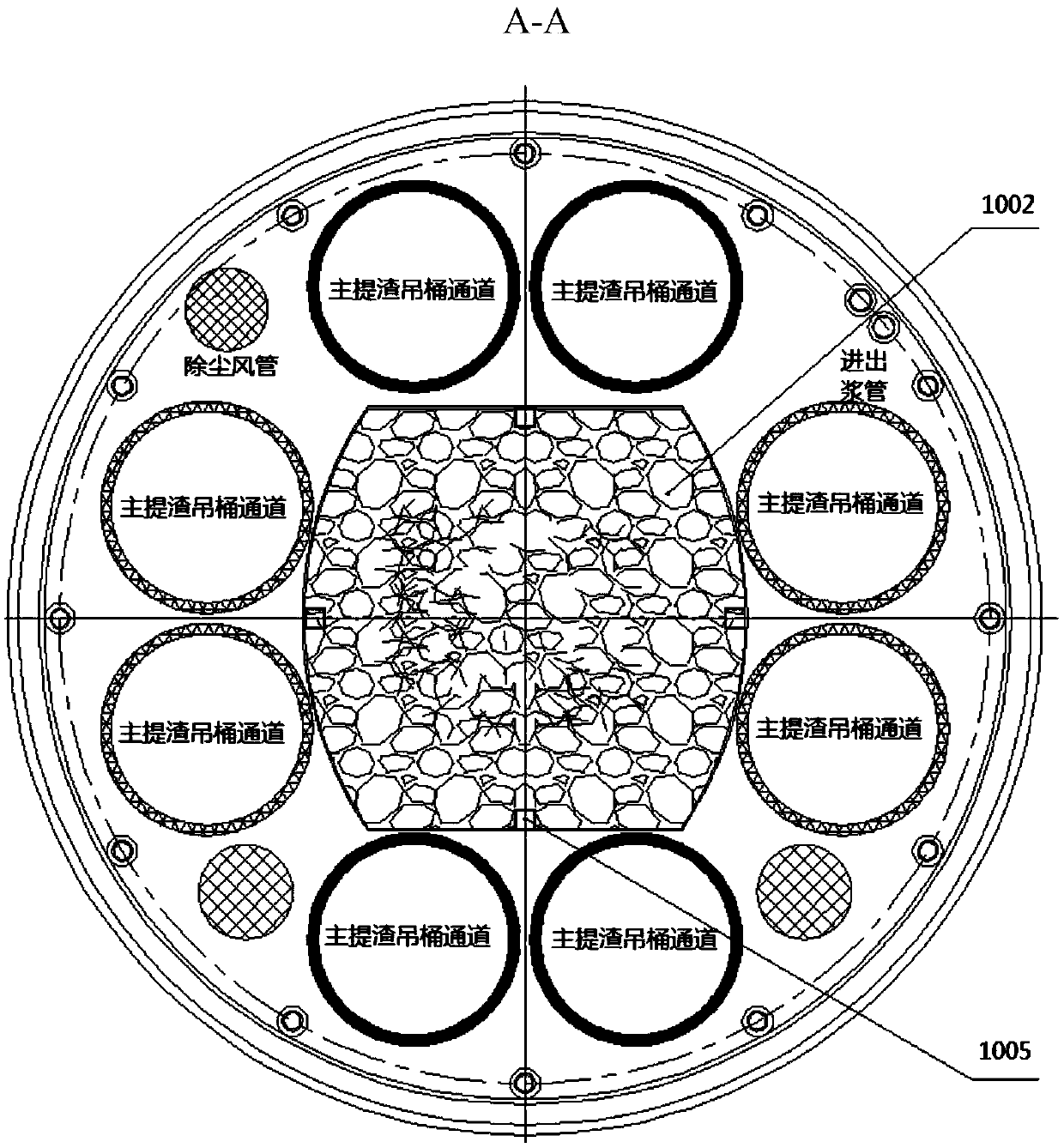
[0027] The core of the present invention is to provide a deep shaft rock boring machine, which can increase the digging depth and further improve the degree of automation and work efficiency by setting up a two-stage boring system to work synchronously.

[0028] In order to enable those skilled in the art to better understand the solution of the present invention, the present invention will be further described in detail below with reference to the accompanying drawings and specific embodiments.

[0029] Please refer to Figure 1 to Figure 8 , figure 1 It is a schematic diagram of the overall structure of a specific implementation of the deep shaft rock tunneling machine provided by the present invention; figure 2 It is a schematic structural diagram of a first-level tunneling system in a specific embodiment of the deep shaft rock tunneling machine provided by the present invention; image 3 It is a schematic structural diagram of a secondary tunneling system in a specific embodime...


PUM


Abstract

The invention discloses a deep shaft rock tunnel boring machine. The machine comprises a derrick arranged on the ground and an underground device platform, wherein a first-stage slag transfer system,a second-stage tunnel boring system, a second-stage slag discharge system, a first-stage slag discharge system and a first-stage tunnel boring system are sequentially arranged below the device platform, the first-stage tunnel boring system is used for expanding the depth of the shaft, the second-stage tunnel boring system is used for expanding the width of the shaft, the first-stage slag dischargesystem conveys the rock slag generated by the excavation of the first-stage tunnel boring system to the first-stage slag transfer system, the second-stage slag discharge system conveys the rock slaggenerated by the excavation of the second-stage tunnel boring system to the first-stage slag transfer system, and the first-stage slag transfer system is used for discharging the rock slag. By arranging the synchronous work of the second-stage tunnel boring system, the depth and the width of the shaft are simultaneously expanded, the hierarchical excavation effectively increases the excavation depth; and by arranging the slag discharge system and the slag transfer system, the slag discharge operation can be completed in the excavation process, so that the automation degree and the working efficiency are further improved.

Description

Technical field [0001] The invention relates to the field of engineering machinery, in particular to a deep shaft rock boring machine. Background technique [0002] Shaft excavation is required in various projects. Existing shaft excavation methods have experienced long-term development. The main sinking methods include drilling and blasting and drilling methods. Shaft excavation equipment has also experienced the same development process, but no major breakthrough has been achieved. The existing shaft boring machine is generally provided with only one boring system at the bottom to achieve depth and width expansion. However, this kind of equipment is difficult to automate, with numerous procedures, cumbersome construction, low sinking efficiency, high manual labor intensity, and most importantly, the limited excavation depth makes it difficult to realize deep shaft construction. [0003] Therefore, how to provide a deep shaft rock boring machine with a high degree of automation a...

Claims


Application Information

Patent Timeline
IPC IPC(8): E21D1/03E21D1/06
CPCE21D1/03E21D1/06
Inventor 刘飞香程永亮何其平彭正阳龙斌韩佳霖姚满黄强江志强
Owner CHINA RAILWAY CONSTR HEAVY IND
Learn More