Device and method for measuring engine valve movement law in complex oil mist environment

A technology of engine valves and movement rules, which is applied in the direction of measuring devices, engine testing, and machine/structural component testing, etc. It can solve the problems that the measuring device is not suitable for accurate measurement, etc., so as to reduce the quality of lubricating oil, reduce accumulation, and improve accuracy Effect

Active Publication Date: 2020-02-21
HUAZHONG UNIV OF SCI & TECH
View PDF7 Cites 0 Cited by
  • Summary
  • Abstract
  • Description
  • Claims
  • Application Information

AI Technical Summary

Problems solved by technology

[0007] Aiming at the above defects or improvement needs of the prior art, the present invention provides a device and method for measuring engine valve movement laws suitable for complex oil mist environments, with the purpose of solving the problem that the existing measuring devices are not suitable for realizing complex oil mist environments. For the problem of accurate measurement, the present invention makes the measuring device suitable for the real-time and accurate measurement of the valve lift law or motion law when the engine is actually running in a complex oil mist environment by setting the oil isolation structure, which has the advantages of simple structure and accurate measurement Etc

Method used


Image

  • Device and method for measuring engine valve movement law in complex oil mist environment
  • Device and method for measuring engine valve movement law in complex oil mist environment
  • Device and method for measuring engine valve movement law in complex oil mist environment

Examples


Embodiment Construction

[0033] In order to make the object, technical solution and advantages of the present invention clearer, the present invention will be further described in detail below in conjunction with the accompanying drawings and embodiments. It should be understood that the specific embodiments described here are only used to explain the present invention, not to limit the present invention. In addition, the technical features involved in the various embodiments of the present invention described below can be combined with each other as long as they do not constitute a conflict with each other.

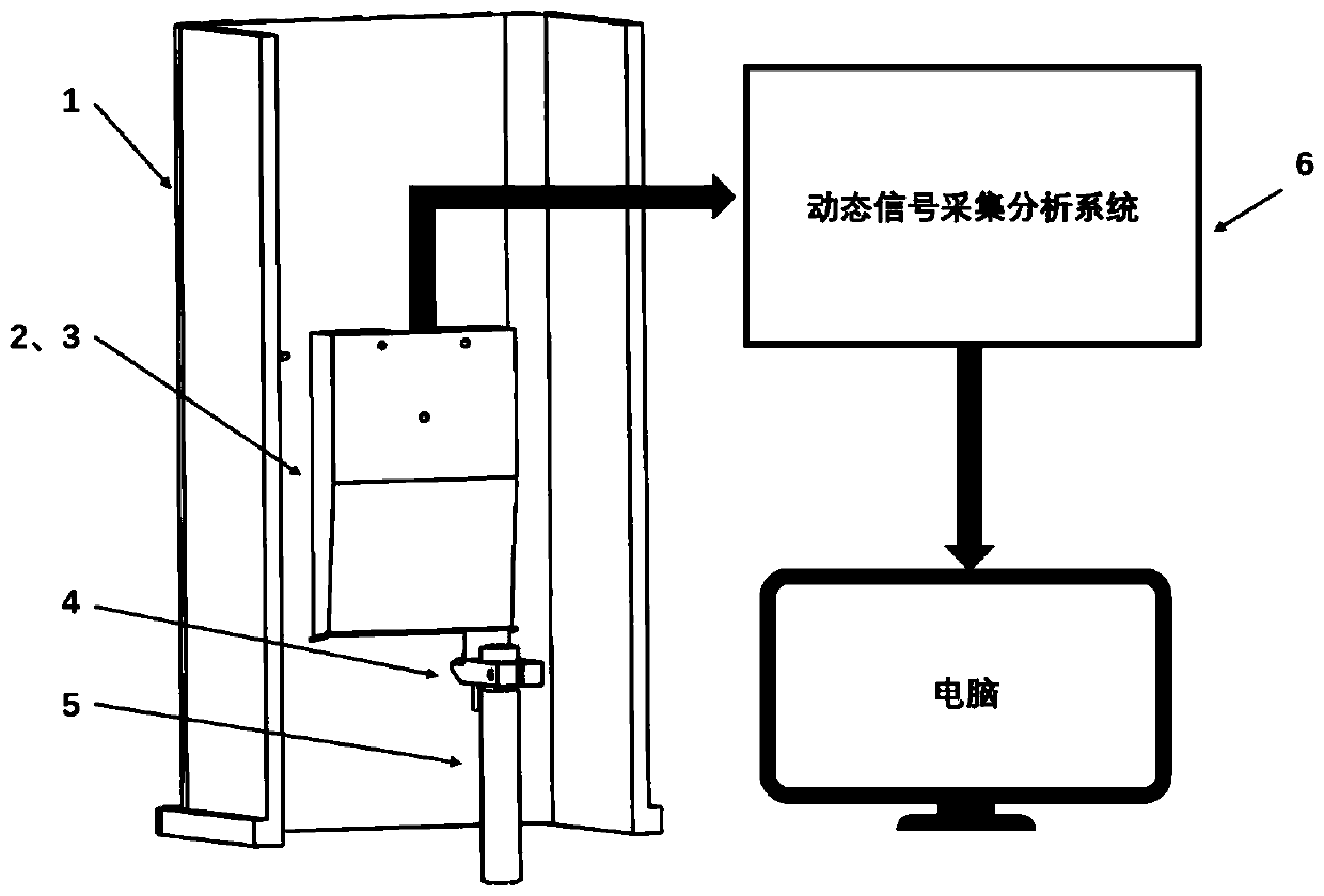
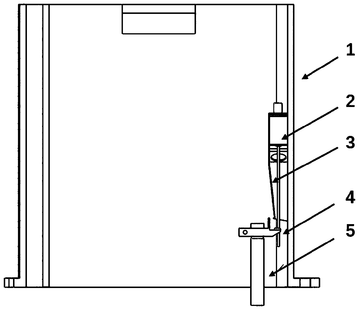
[0034] Such as Figure 1-2 As shown, the embodiment of the present invention provides a device for measuring the movement law of engine valves suitable for complex oil mist environments, which includes a laser displacement sensor 2, a fixed seat 1, a laser light path oil shield 3, a valve clamp block 4 and a dynamic signal Acquisition and analysis system 6, wherein the laser displacement sensor...


PUM


Abstract

The invention belongs to the technical field of engine testing, and particularly discloses an engine valve movement rule measuring device and method for a complex oil mist environment. The device comprise a laser displacement sensor, a fixing seat, a laser light path oil separating cover, a valve clamping block and a dynamic signal collecting and analyzing system, the laser displacement sensor isarranged on the fixing seat and is used for emitting laser, the laser is received by the laser displacement sensor after being scattered on the measuring surface of the valve clamping block, a received laser signal is converted into an electric signal to be transmitted into the dynamic signal collecting and analyzing system, the laser light path oil separating cover covers the outer part of the laser displacement sensor, a valve rod fixing hole is formed in the middle of the valve clamping block, the measuring surface is arranged at one end of the valve clamping block, an oil separating plateand an oil discharging groove are further arranged between the valve rod fixing hole and the measuring surface, and the dynamic signal collecting and analyzing system is connected with the laser displacement sensor. The device and the method are suitable for achieving real-time and accurate measurement of the valve movement rule in the complex oil mist environment, and have the advantages of beingsimple in structure, accurate in measurement and the like.

Description

technical field [0001] The invention belongs to the technical field of engine testing, and more particularly relates to a device and method for measuring engine valve movement law used in complex oil mist environments. Background technique [0002] The gas distribution mechanism is one of the two major moving mechanisms of the engine. It opens or closes the valve regularly according to the working cycle of the engine, so that fresh air enters the cylinder and exhaust gas is discharged from the cylinder to form a reasonable cycle of working fluid. At the same time, it ensures the sealing of the combustion chamber during the compression process and work process of the engine, forming a strong work capacity. The operating state of the valve directly affects the ventilation process of the engine, which in turn affects the combustion performance and emission level of the engine, and plays a vital role in the engine. Therefore, the measurement of the valve movement law under the ...

Claims


Application Information

Patent Timeline
Patent Type & Authority Patents(China)
IPC IPC(8): G01M15/00
CPCG01M15/00
Inventor 王兆文覃国宇成晓北杜涛
Owner HUAZHONG UNIV OF SCI & TECH
Why Eureka
Try Eureka