A visual experimental device for supercritical pressure fluid flow and heat transfer under the condition of equal heat flow heating

A technology for heating conditions and pressure fluids, which is applied in measurement devices, flow characteristics, thermal development of materials, etc. It can solve the problems of inability to realize visual measurement of medium flow, inability to obtain supercritical pressure fluids, and limited pressure-bearing capacity of rectangular channels. The effect of high hardness, strong bearing capacity and high thermal conductivity

Active Publication Date: 2020-12-01
BEIHANG UNIV
View PDF5 Cites 0 Cited by
  • Summary
  • Abstract
  • Description
  • Claims
  • Application Information

AI Technical Summary

Problems solved by technology

Although the academic circles have been studying the flow and heat transfer of supercritical pressure fluids for many years, because the process is affected by multiple coupling factors (experimental objects and boundary conditions such as structure, flow, and heat transfer), the specific influence mechanism of each factor is still unclear. , simultaneous heat transfer characteristic experiment and flow visualization measurement is undoubtedly an important research approach to explore its flow heat transfer mechanism
[0003] At present, the heat transfer visualization research of supercritical pressure fluid is mostly realized through the circular pipeline window with good pressure bearing, which has the advantages of simple structure, convenient connection and high pressure resistance. After the pipeline, the visual measurement of the flow of the medium under heating conditions cannot be realized, and the key information of the abnormal heat transfer of the supercritical pressure fluid and the flow pulsation cannot be accurately obtained from the flow morphology
In addition, some studies have also realized the visual measurement of the flowing medium in the rectangular cross-section channel under the condition of heating, but due to the limited pressure bearing capacity of the rectangular channel, most of the relevant research is oriented to low pressure conditions, and its application range is limited

Method used


Image

  • A visual experimental device for supercritical pressure fluid flow and heat transfer under the condition of equal heat flow heating
  • A visual experimental device for supercritical pressure fluid flow and heat transfer under the condition of equal heat flow heating
  • A visual experimental device for supercritical pressure fluid flow and heat transfer under the condition of equal heat flow heating

Examples


Embodiment Construction

[0035] In the following, only some exemplary embodiments are briefly described. As those skilled in the art would realize, the described embodiments may be modified in various different ways, all without departing from the spirit or scope of the present invention. Accordingly, the drawings and descriptions are to be regarded as illustrative in nature and not restrictive.

[0036] The present invention will be described in detail below in conjunction with the accompanying drawings.

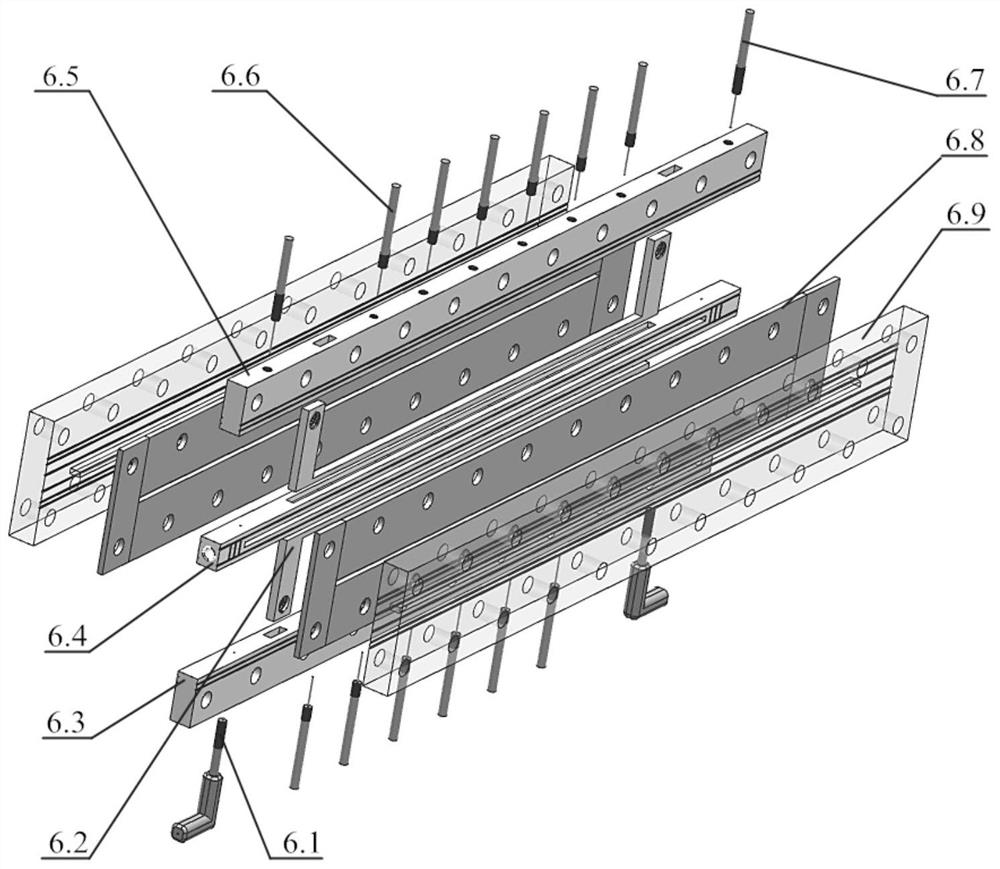
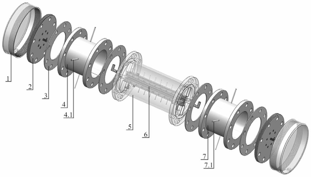
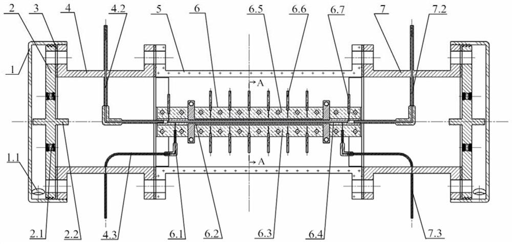
[0037] Such as Figure 1-Figure 4 As shown in FIG. 1 , it shows the heat transfer visualization experimental device for supercritical pressure fluid flow provided by the present invention under the condition of constant heat flux heating. The device includes two parts: the inner flow heat transfer experiment section and the outer pressure protection chamber. Flow heat transfer experiment section 6 includes pressure measuring tube 6.1, metal heating strip 6.2, lower gland 6.3, fluid channel skelet...


PUM

PropertyMeasurementUnit
hardnessaaaaaaaaaa
thermal conductivityaaaaaaaaaa
compressive strengthaaaaaaaaaa

Abstract

The invention provides a supercritical pressure fluid flow and heat transfer visualized experimental device under a constant heat flux heating condition, which belongs to the field of supercritical pressure fluid flow and heat transfer. The characteristics of convective heat transfer, pulsating flow and the like of the supercritical pressure fluid in a rectangular channel under effects of couplingof multi-boundary conditions and flow pattern characteristics can be investigated, and an experimental data support is provided for clarifying a physical mechanism and triggering conditions for abnormal supercritical pressure fluid heat transfer and pulsating flow phenomena.

Description

technical field [0001] The invention belongs to the field of flow and heat transfer of supercritical pressure fluid, and in particular relates to an experimental device for studying the convective heat transfer and pulsating flow characteristics of supercritical pressure fluid in a rectangular channel under the coupling effect of multiple boundary conditions, as well as the characteristics of flow form, especially relates to an experimental device. The utility model relates to a visual experimental device for supercritical pressure fluid flow and heat transfer under the condition of equal heat flow heating. Background technique [0002] Supercritical pressure fluids have been applied in many industrial fields, including supercritical steam power plants, nuclear reactor cooling water systems, supercritical water oxidation, aircraft engine thermal protection, supercritical carbon dioxide cycle, supercritical organic Rankine cycle, etc. For the heat transfer process, since the ...

Claims


Application Information

Patent Timeline
Patent Type & Authority Patents(China)
IPC IPC(8): G01N11/00G01N25/20
CPCG01N11/00G01N25/20
Inventor 董苯思徐国强付建全永凯闻洁付衍琛
Owner BEIHANG UNIV
Why Eureka
Try Eureka