Flexible refractive film patch with microstructure

A microstructure and film technology, applied in the field of refractive films, to achieve the effects of alleviating peripheral defocus, various design forms, and flexible shapes

Inactive Publication Date: 2019-04-16
WENZHOU MEDICAL UNIV
View PDF5 Cites 14 Cited by
  • Summary
  • Abstract
  • Description
  • Claims
  • Application Information

AI Technical Summary

Problems solved by technology

Film patches have obvious advantages, but they have not been combined

Method used


Image

  • Flexible refractive film patch with microstructure
  • Flexible refractive film patch with microstructure
  • Flexible refractive film patch with microstructure

Examples


Embodiment Construction

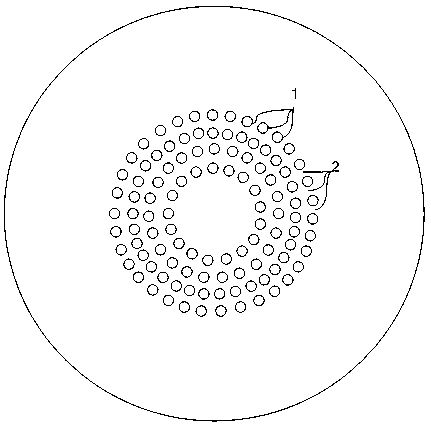
[0033] Combine now figure 1 , figure 2 , image 3 , Figure 4 , Figure 5 , Figure 6 , Figure 7 , Figure 8 The present invention is further described, as figure 1 As shown, the flexible refractive film patch with microstructure implemented by the present invention has three independent working areas, which are respectively the central optical area of ​​zero diopter and zero prism power, and the microstructure annular zone with microlens array distribution zone, and a peripheral optic zone that has the same physical properties as the central optic zone. Wherein, the microlens array in the distribution area of ​​the microstructure annular zone is composed of a plurality of microlens structures arranged in a certain order, and each microlens has a stable refractive power.

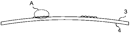
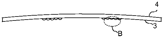
[0034] Such as figure 2 and image 3 As shown, the film patch has two sides, one side is the sticking side, and the other side is the refractive function side. The film patch also has a certain...


PUM


Abstract

The invention relates to a flexible refractive film patch with a microstructure. Besides having the performance of a conventional film patch, the flexible refractive film patch has a certain refractive effect in a prescribed area; after being attached onto the spectacle lens of a spectacle frame, the flexible refractive film maintains a good refractive correction effect at the central region of the spectacle lens; and the flexible refractive film patch can also realize peripheral defocusing, and therefore, the flexible refractive film patch can alleviate the peripheral defocusing effect of theretina of a person who wears glasses. The film patch of the invention can be applied to various spectacle lenses, and is flexible and variable in shape; and the micro-structured ring zone distribution area of the film patch can be designed into various forms, and therefore, the correction needs of different groups can be met.

Description

technical field [0001] The invention specifically relates to the technical field of refractive films, in particular to a flexible refractive film patch with a microstructure. Background technique [0002] Peripheral retinal defocus refers to the state of refractive error existing around the retina after the incident light is focused by the refractive system of the human eye. Most myopia patients have hyperopic defocus around the retina, and both clinical studies and experimental animal myopia models have found that this hyperopic defocus around the retina of myopia patients may play a key role in the occurrence and development of myopia. [0003] At present, the peripheral defocus correction lens designed and developed based on the above theory on the market is to maintain the central refractive correction amount and add peripheral diopters to achieve the purpose of correcting the overall peripheral defocus. This kind of frame glasses for correcting peripheral defocus will ...

Claims


Application Information

Patent Timeline
IPC IPC(8): G02C7/08G02B3/00
CPCG02B3/0037G02C7/08
Inventor 厉以宇陈娇洁毛欣杰陈浩
Owner WENZHOU MEDICAL UNIV
Why Eureka
Try Eureka