Supercharge Your Innovation With Domain-Expert AI Agents!

LCD detection device

A detection equipment and detection head technology, applied in nonlinear optics, instruments, optics, etc., can solve problems such as incorrect detection results, and achieve the effect of saving equipment costs and improving detection efficiency

Pending Publication Date: 2019-04-16
SUZHOU JINGLAI OPTO CO LTD
View PDF0 Cites 1 Cited by
  • Summary
  • Abstract
  • Description
  • Claims
  • Application Information

AI Technical Summary

Problems solved by technology

At present, the line scan and UV glue detection are detected separately on different devices, because if the detection is performed on the same device, the camera for UV glue detection will be interfered by the side light source of the line scan, resulting in incorrect detection results

Method used


Image

  • LCD detection device
  • LCD detection device
  • LCD detection device

Examples


Embodiment Construction

[0026] The technical solutions of the present invention will be further described below in conjunction with the accompanying drawings and through specific implementation methods.

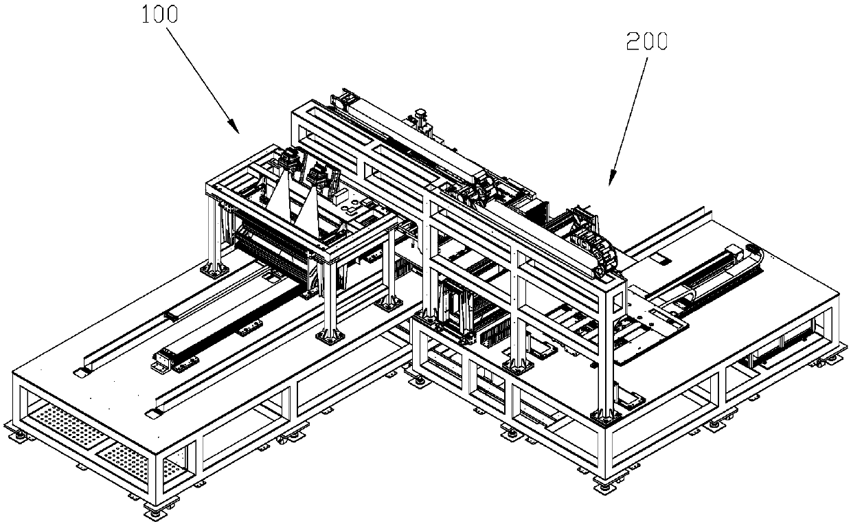
[0027] Such as figure 1 As shown, the LCD detection equipment of the present invention comprises a first detection device 100 and a second detection device 200, and the first detection device 100 is used for LCD300 (see image 3 ) to perform on-line scanning, PCB board detection and UV glue detection, and the second detection device 200 is used to perform off-line scanning on the LCD 300 .

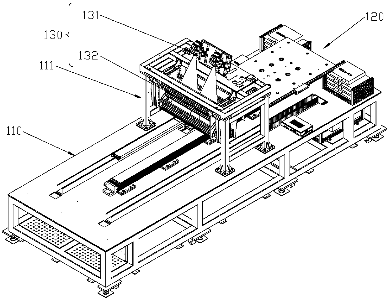
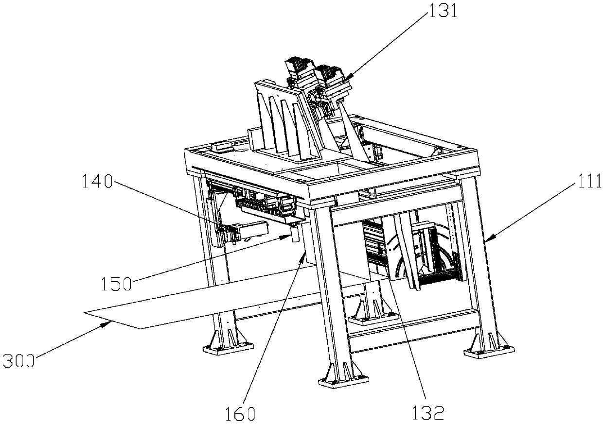
[0028] Specifically, such as Figure 2 to Figure 3 As shown, the first detection device 100 includes a first machine platform 110, a first conveying mechanism 120 arranged on the first machine platform 110, and an upper line sweep mechanism 130 arranged on the first machine platform 110 and above the first conveying mechanism 120 , PCB board detection mechanism 140 and UV glue detection mechanism 150, and a li...


PUM


Abstract

The invention relates to the technical field of liquid crystal panel detection and discloses an LCD detection device, comprising a first detection device, wherein the first detection device comprisesa first machine table, a first conveying mechanism arranged on the first machine table, and an upper linear scanning mechanism, a PCB detection mechanism and a UV glue detection mechanism which are arranged on the first machine table and located above the first conveying mechanism, and a shading curtain is arranged between the upper linear scanning mechanism and the UV glue detection mechanism. According to the LCD detection equipment disclosed by the invention, the shading curtain is arranged between the upper linear scanning mechanism and the UV glue detection mechanism; and a side light source of the upper linear scanning mechanism can be prevented from interfering with a camera of the UV glue detection mechanism, so that linear scanning, PCB detection and UV glue detection can be carried out on the same equipment, the equipment cost is saved, and the detection efficiency is greatly improved.

Description

technical field [0001] The invention relates to the technical field of liquid crystal panel detection, in particular to an LCD detection device. Background technique [0002] LCD (Liquid Crystal Display) liquid crystal display, its structure is to place a liquid crystal cell among two parallel glass substrates, set a TFT (thin film transistor) on the lower glass substrate, and set a color filter on the upper glass substrate. After the LCD is processed, it needs to be inspected for appearance. The appearance inspection of LCD includes line scanning, PCB board inspection and UV glue inspection. Line scanning includes online scanning and offline scanning. At present, line scanning and UV glue inspection are performed separately on different devices, because if the inspection is performed on the same device, the camera for UV glue inspection will be interfered by the side light source of the line scanning, resulting in incorrect detection results. [0003] In view of the above-...

Claims


Application Information

Patent Timeline
IPC IPC(8): G02F1/13
CPCG02F1/1309
Inventor 祝鹏程
Owner SUZHOU JINGLAI OPTO CO LTD
Features
  • R&D
  • Intellectual Property
  • Life Sciences
  • Materials
  • Tech Scout
  • Unparalleled Data Quality
  • Higher Quality Content
  • 60% Fewer Hallucinations
Learn More