
Cooling system and terminal equipment

A technology of terminal equipment and heat dissipation system, which is applied to structural parts of electrical equipment, cooling/ventilation/heating transformation, electrical components, etc. Efficiency, improved heat dissipation, flexible and simple control methods

Inactive Publication Date: 2021-01-26
BOE TECH GRP CO LTD +1
View PDF8 Cites 0 Cited by
  • Summary
  • Abstract
  • Description
  • Claims
  • Application Information

AI Technical Summary

Problems solved by technology

However, due to the small space inside the mobile phone, only through conduction heat dissipation, the heat dissipation effect is poor, which reduces the service life of the mobile phone; moreover, the heat generated inside the mobile phone will be transferred to the shell, causing the shell temperature to be too high

Method used


Image

  • Cooling system and terminal equipment
  • Cooling system and terminal equipment
  • Cooling system and terminal equipment

Examples


Embodiment Construction

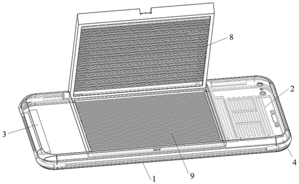
[0044] Example embodiments will now be described more fully with reference to the accompanying drawings. Example embodiments may, however, be embodied in many forms and should not be construed as limited to the embodiments set forth herein; rather, these embodiments are provided so that this disclosure will be thorough and complete, and will fully convey the concept of example embodiments to those skilled in the art. The same reference numerals in the drawings denote the same or similar structures, and thus their detailed descriptions will be omitted.

[0045] Embodiments of the present disclosure provide a heat dissipation system, which is applied to a terminal device and used to dissipate heat for the terminal device. The terminal equipment in this disclosure refers to equipment that inputs programs and data to computers or receives computer output processing results through communication facilities, such as mobile phones, tablet computers, notebook computers, walkie-talkie...


PUM


Abstract

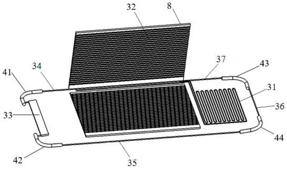
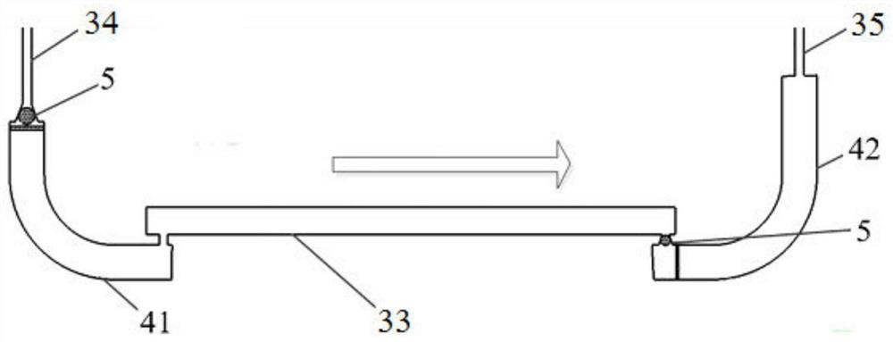
The invention provides a heat dissipation system and terminal equipment, and the heat dissipation system is applied to the terminal equipment, and comprises a circulation pipe and a one-way valve installed on the circulation pipe, wherein the circulation pipe is used for containing a heat exchange medium and allowing the heat exchange medium to flow circularly. The circulation pipe comprises a heat dissipation section and at least one air bag section, wherein the air bag sections are made of elastic materials. The one-way valve is used for enabling the heat exchange medium to flow circularly in one direction. The internal air pressure is changed by pressing the air bag sections, so as to promote the directional flowing of the heat exchange medium in the circulation pipe, thereby improvingthe heat dissipation efficiency. In addition, the heat dissipation effect can be adjusted at any time according to conditions during use, and the control mode is flexible, simple and convenient.

Description

technical field [0001] The present disclosure relates to the technical field of terminal equipment, in particular, to a heat dissipation system, and to a terminal equipment. Background technique [0002] As the main frequency of mobile phones, tablet computers, notebook computers and other electronic products is getting higher and higher, the power consumption is getting higher and higher, and the heat generation is getting higher and higher. Moreover, these electronic products are often smaller and smaller, and most of them adopt an integrated design. The heat generated by them accumulates in the small internal space and cannot be effectively dissipated. [0003] For example, in a mobile phone, a heat dissipation material in contact with the main board of the mobile phone is arranged inside, and local hot spots are diffused through thermal contact conduction. However, due to the small space inside the mobile phone, the heat dissipation effect is poor only through conductio...

Claims


Application Information

Patent Timeline
Patent Type & Authority Patents(China)
IPC IPC(8): H05K7/20
CPCH05K7/20327H05K7/20381
Inventor 郭少飞李中华郝东佳阮益平王世鹏桑建
Owner BOE TECH GRP CO LTD
Learn More