
Ultrasound wave source azimuth orienting device, and method of analyzing superimposed image

A calibration device and overlapping image technology, applied to direction finders, measuring devices, and radio wave measurement systems using ultrasonic/sonic/infrasonic waves, can solve the problem of easily causing grating lobes, making it difficult to accurately determine the direction of the sound source, and difficult Increase the number of microphones and other issues to achieve the effect of easy handling and reduced impact

Active Publication Date: 2019-04-16
JFE STEEL CORP +1
View PDF16 Cites 2 Cited by
  • Summary
  • Abstract
  • Description
  • Claims
  • Application Information

AI Technical Summary

Problems solved by technology

However, in this case, there is a problem that although the direction of arrival of the ultrasonic wave can be determined, the ultrasonic wave can only be measured within a point-like range.
However, in this structure, it is difficult to increase the number of microphones, and from the viewpoint of beamforming, the directivity is wide, and it is difficult to improve the accuracy of azimuth calibration
[0018] In the case where the distance between the microphones does not satisfy the above formula (2), there is also the following problem. The more the search range of ultrasonic waves is measured at one time by using multiple microphones, the more likely it is to cause grating lobes.
[0019] As such, in the prior art, if a beamforming method using multiple microphones is used to calibrate the direction of an ultrasonic source with a short wavelength, the occurrence of grating lobes cannot be suppressed, and it is difficult to accurately identify the sound source. issues such as orientation
[0020] Furthermore, in order to perform signal processing on high-frequency ultrasonic waves, it is necessary to sample the received ultrasonic waves at high speed, but for the beamforming method that usually uses multiple receiving elements, it is difficult to balance the update speed of sufficient signal processing results with the high speed sampling

Method used


Image

  • Ultrasound wave source azimuth orienting device, and method of analyzing superimposed image
  • Ultrasound wave source azimuth orienting device, and method of analyzing superimposed image
  • Ultrasound wave source azimuth orienting device, and method of analyzing superimposed image

Examples


Embodiment 1

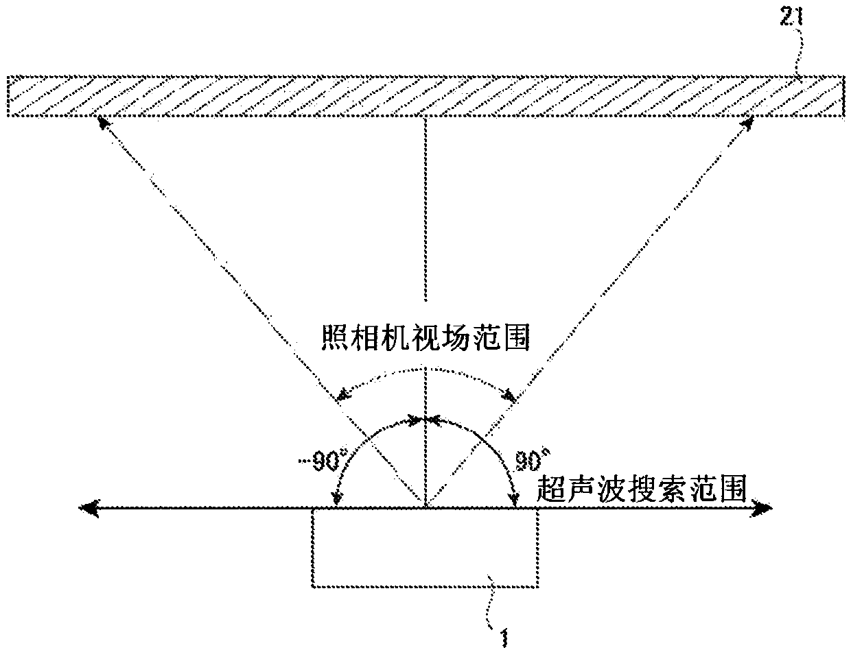
[0087] The azimuth calibration device involved in the present invention is used to perform azimuth calibration of the ultrasonic source. As the sensor constituting the array sensor, MA40H1S-R (Murata Manufacturing Co., Ltd.) is used, and the arrangement of the sensor is as follows Figure 4 As in (a), all the sensor intervals are unified at 5.6mm. The inspection object is the gas piping equipment in the ironworks. The distance from the measurement object was set to 15.7 m, and the frequency of the ultrasonic wave used as the measurement object was 40 kHz. The dimensionless sensor interval is obtained by 5.6 (mm) / 8.5 (mm) to be about 0.66. In addition, the field of view range of the camera and the search range of the array sensor are within ±25° in the horizontal direction and within ±15° in the vertical direction.

[0088] Figure 9 It is a superimposed image obtained by Example 1. exist Figure 9 In the figure, the part of the dark black part surrounded by the black dot...

Embodiment 2

[0090] Use separately Figure 4 The sensor configuration shown in (a) (set as configuration A.) azimuth calibration device, and Figure 4 Overlay images were created for the azimuth calibration device with the sensor configuration shown in (b) (set as configuration B). Conditions such as the type of sensor and the interval between sensors are the same as those in Example 1.

[0091] Figure 10 It is an enlarged view of a superimposed image obtained in Example 2. Figure 10 (a) is an enlarged view of the overlapped image obtained by configuring the azimuth calibration device of A, Figure 10 (b) is an enlarged view of the overlapping image obtained by configuring the azimuth calibration device of B. exist Figure 10 In the case of the arrangement A shown in (a), in addition to the ultrasonic source 52 observed at the upper right of the drawing, virtual image regions 54 with high sound pressure are also seen at the lower right and upper left of the drawing. while in Figu...

Embodiment 3

[0093] The azimuth calibration device according to the present embodiment was pointed at the measuring object of the simulated pipe leakage in which two points were set, and superimposed images were acquired. As the azimuth calibration device, configuration B of Embodiment 2 was used.

[0094] Figure 11 It is an analysis diagram of superimposed images obtained in Example 3. exist Figure 11 In , the high-sound-pressure region 60 in which the sound pressure in the obtained superimposed image is equal to or greater than a predetermined value is color-coded and shown. In the superimposed image, a position 62 where the simulated piping leaks is marked with a white circle, a position 64 where the sound pressure becomes maximum is indicated by a white dotted line square, and a high temperature pressure region 60 is indicated by a black dotted line.

[0095] Figure 12 It is an analysis diagram of superimposed images obtained in Example 3. exist Figure 12 In the example shown, ...


PUM


Abstract

Provided is an ultrasound wave source azimuth orienting device capable of measuring an ultrasound wave sound source azimuth over a wide search range at one time, while being compact and reducing the impact of a grating lobe. The ultrasound wave source azimuth orienting device comprises: a camera which captures an image of an object being measured; an array sensor which measures the sound pressureof an ultrasound wave emitted from the direction of the object being measured; a computing means which generates a sound pressure map on the basis of sound pressure information relating to the ultrasound wave acquired by the array sensor, and generates a superimposed image in which the sound pressure map and a captured image acquired by the camera are superimposed; and a display means for displaying the superimposed image; wherein the array sensor comprises a total of at least 9 and at most 25 surface-mounted sensors at least some of which are provided on an X-axis and a Y-axis in the same plane.

Description

technical field [0001] The present invention relates to an ultrasonic source azimuth calibration device which is small in size and has less erroneous determination due to grating lobes, and an analysis method of overlapping images using the ultrasonic source azimuth calibration device. Background technique [0002] In ironworks, for example, it is necessary to promptly detect the occurrence of corrosion holes in piping, deterioration of electrical equipment, and the like, and perform repairs. In order to detect them, sound waves released when gas leaks from corrosion holes in pipes or corona discharges in electrical equipment are measured. When measuring sound waves in the audible area, abnormalities may not be accurately detected due to the influence of ambient noise and the like. Therefore, ultrasonic waves are usually measured in order to detect abnormalities in various devices. [0003] A technique is known in which a plurality of sensors are used to calibrate the direc...

Claims


Application Information

Patent Timeline
Patent Type & Authority Applications(China)
IPC IPC(8): G01S3/802G01H3/00G01S7/56
CPCG01H3/00G01S3/802G01S7/56G01H3/125
Inventor 林弘治末长清佳前川翔之介小田将广尾国道弘栉田靖夫
Owner JFE STEEL CORP
Learn More