Polymer devolatilization device

A devolatilization device and polymer technology, applied in cascade evaporators, vertical tube evaporators, evaporator accessories, etc., can solve the problems of large device footprint, power consumption cost, high cost, short heating time, The effect of avoiding polymer decomposition and increasing the heat transfer area

Pending Publication Date: 2019-04-19
上海宥壹化工科技有限公司
View PDF0 Cites 3 Cited by
  • Summary
  • Abstract
  • Description
  • Claims
  • Application Information

AI Technical Summary

Problems solved by technology

However, in the prior art, each equipment is separated, and the equipment is connected by pipelines, which leads to the following disadvantages: (1) the cost of equipment purchase...

Method used


Image

  • Polymer devolatilization device
  • Polymer devolatilization device

Examples


Embodiment Construction

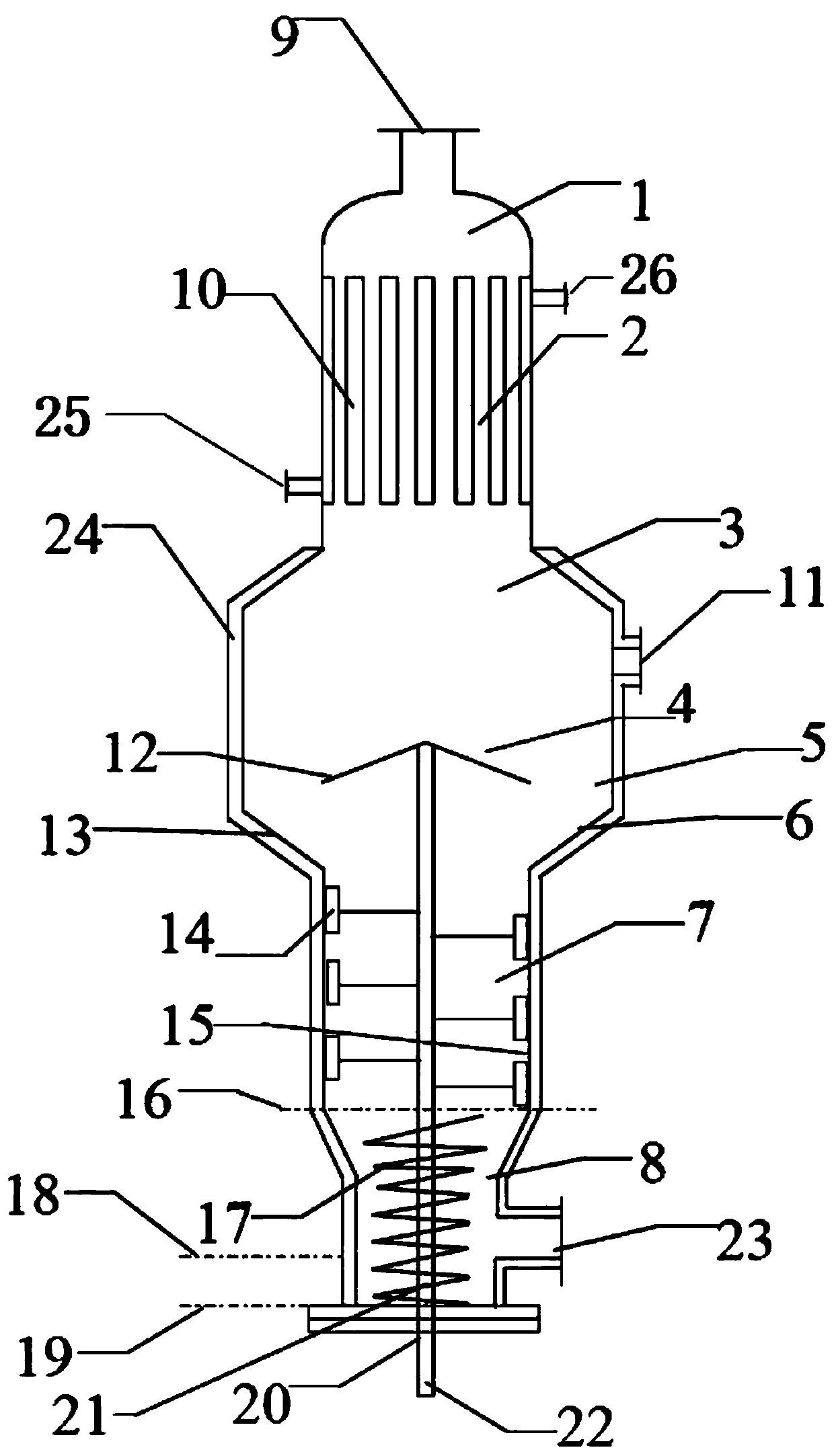
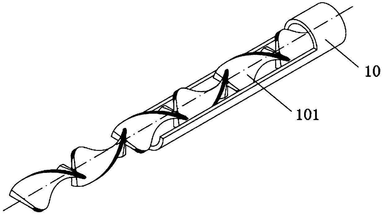
[0028] The advantages of the present invention will be further elaborated below in conjunction with the accompanying drawings and specific embodiments.

[0029]Reference will now be made in detail to the exemplary embodiments, examples of which are illustrated in the accompanying drawings. When the following description refers to the accompanying drawings, the same numerals in different drawings refer to the same or similar elements unless otherwise indicated. The implementations described in the following exemplary examples do not represent all implementations consistent with the present disclosure. Rather, they are merely examples of apparatuses and methods consistent with aspects of the present disclosure as recited in the appended claims.

[0030] The terminology used in the present disclosure is for the purpose of describing particular embodiments only, and is not intended to limit the present disclosure. As used in this disclosure and the appended claims, the singular ...


PUM


Abstract

The invention provides a polymer devolatilization device. The devolatilization device is sequentially provided with a feeding distribution area, a heating devolatilization area, a first falling stripdevolatilization area, a first falling film devolatilization area, a second falling strip devolatilization area, a second falling film devolatilization area and a material collection region. The feeding distribution area is provided with a feeding hole, a shell-and-tube heat exchanger is arranged in the heating devolatilization area, and the pipe layer of the shell-and-tube heat exchanger includesseveral heating row tubes, wherein the upper portions of the heating row tubes are used for feeding, and the lower portions of the heating row tubes are used for discharging; a volatile component outlet is formed in the first falling film devolatilization area, a liquid collection falling film distributor is arranged in the first falling film devolatilization area, and the liquid collection falling film distributor is connected with a motor outside the bottom of the devolatilization device through a rotating shaft, the bottom surface of the side face of the material collection region is provided with a discharge hole, and the material collection region is provided with a push device used for pushing polymer to move downwards. According to the technical scheme, the devolatilization deviceis compact in structure and small in size, and the device can be used for static and dynamic multi-stage high efficiency devolatilization of the polymer at the appropriate process temperature.

Description

technical field [0001] The invention relates to the technical field of polymer devolatilization, in particular to a polymer devolatilization device. Background technique [0002] The polymers coming out of the reactor all contain low molecular weight components, such as monomers, solvents and reaction by-products, which are collectively referred to as volatiles, which should not be contained in the polymer. The process of removing volatiles from polymer solution or polymer bulk is called polymer devolatilization. This process can meet health and environmental requirements while improving polymer performance. It has become a part of the polymer production process. One of the necessary unit operations. [0003] Industrial devolatilization equipment can be divided into two categories: static type and dynamic type. Static devolatilization equipment has no mechanical stirring or mechanical stirring is not important for the separation of volatiles from polymers. The usual types ...

Claims


Application Information

Patent Timeline
IPC IPC(8): B01D1/06B01D1/22B01D1/30
CPCB01D1/0088B01D1/0011B01D1/06B01D1/22B01D1/30
Inventor 单岩崑马永明李蒙
Owner 上海宥壹化工科技有限公司
Why Eureka
Try Eureka