
Processing method for special-shaped light guide plate injection mold

A processing method and injection mold technology, applied in the processing field of injection molds for special-shaped light guide plates, can solve problems affecting production efficiency, destroying V-cut grooves, and increasing workload, so as to save manpower and material resources, reduce cleaning difficulty, and speed up The effect of production efficiency

Active Publication Date: 2019-04-19
SHENZHEN LONGLI TECH CO LTD
View PDF5 Cites 6 Cited by
  • Summary
  • Abstract
  • Description
  • Claims
  • Application Information

AI Technical Summary

Problems solved by technology

During the mold repairing process, the wire cutting method is still used to finish the special-shaped structure of the initial mold, but the wire cutting method will destroy the V-cut groove during the finishing process, especially the V-cut groove at the tail, resulting in the need for follow-up Re-making the V-cut groove, and sometimes due to deviation problems, it has to go back and forth to repair the mold many times, which increases a lot of workload and seriously affects production efficiency
In addition, since the plate is wire-cut in dielectric fluid, the V-cut groove will have stains during processing, which is difficult to clean and affects the structure of the V-cut groove of the mold
[0004] Due to the precise structure of the machine tool, high technical content and high machine price, the cost of use is also high
In the process of repeated mold repair, remaking the V-cut groove also increases the material cost and labor cost, and the wire cutting part will produce a ridge during the wire cutting process, which needs to be polished after the mold is repaired, and there are many steps

Method used


Image

  • Processing method for special-shaped light guide plate injection mold
  • Processing method for special-shaped light guide plate injection mold
  • Processing method for special-shaped light guide plate injection mold

Examples


Embodiment Construction

[0041] For better understanding and implementation, the specific implementation manners of the present invention will be further described in detail below in conjunction with the accompanying drawings and embodiments. The following examples are only used to illustrate the present invention and are not intended to limit the scope of the present invention.

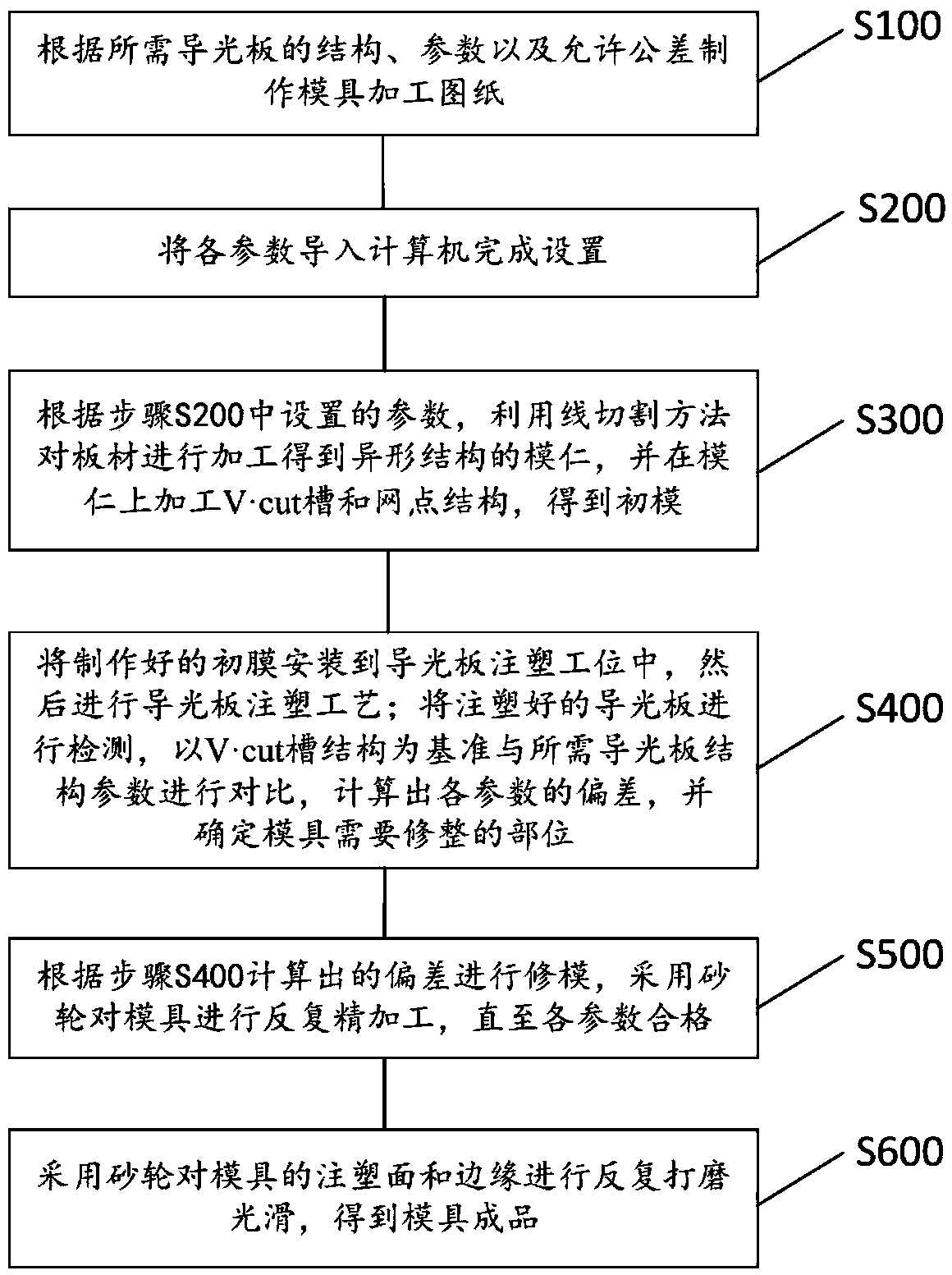
[0042] Please also refer to Figure 1 to Figure 4 , the processing method of an injection mold for a special-shaped light guide plate provided by the present invention will now be described. The above-mentioned processing method of a light guide plate injection mold includes steps S100-S600:

[0043] S100: Make mold processing drawings according to the structural parameters and allowable tolerances of the required light guide plate;

[0044] S200: Import the structural parameters into the computer to complete the setting;

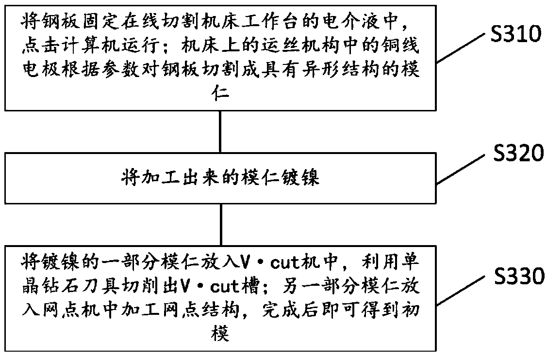
[0045] S300: According to the structural parameters set in step B, process the sheet material by a ...


PUM

PropertyMeasurementUnit
thicknessaaaaaaaaaa
widthaaaaaaaaaa
depthaaaaaaaaaa

Abstract

The invention discloses a processing method for a special-shaped light guide plate injection mold. The processing method for the special-shaped light guide plate injection mold comprises drawing, importing parameters into a computer, starting linear cutting equipment to manufacture a mold insert, conducting nickel plating, manufacturing a V-cut groove to obtain a primary mold, carrying out a moldtest, trimming the mold with specific grinding wheels, and removing burrs on the mold. According to the processing method for the special-shaped light guide plate injection mold, in the production process of the injection mold, a linear cutting method is adopted to manufacture the primary mold and then the grinding wheels are used for finish machining in the mold trimming process. The processing method is simple to operate and does not damage the V-cut groove, and the grinding wheels are used for trimming, so that the burrs on the edge of the mold can be all removed and the labor cost is saved.

Description

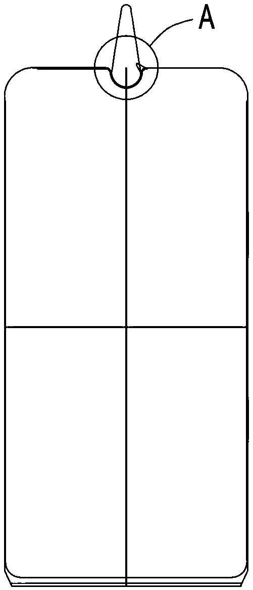
technical field [0001] The invention relates to the technical field of injection molds for light guide plates, in particular to a processing method for injection molds for special-shaped light guide plates. Background technique [0002] In order to increase the ratio of the display screen in existing full-screen mobile phones, one method usually adopted is to move the front camera, earpiece hole and other components of the mobile phone from the body to the display screen, so in order to make the display screen accommodate the front For components such as the camera and the earpiece hole, a gap needs to be set at one end of the light guide plate, such as notch screen, beauty tip, water drop screen, etc. At present, one method of producing this kind of special-shaped light guide plate is to change the structure of the mold so that the injection-molded light guide plate has a gap, and the premise of producing the special-shaped light guide plate is to make an injection mold. ...

Claims


Application Information

Patent Timeline
Patent Type & Authority Applications(China)
IPC IPC(8): B23P15/24
CPCB23P15/24
Inventor 张小齐叶良松卢志坚
Owner SHENZHEN LONGLI TECH CO LTD
Learn More