Mechanical gripper with adjustable width

A manipulator gripper and adjustable technology, applied in the field of manipulator grippers, can solve the problems of processing stagnation, low processing efficiency, and high error rate of pneumatic grippers, and achieve the effects of reducing loss, improving safety, and improving accuracy.

Pending Publication Date: 2019-04-19
宁波开浦智能科技有限公司
View PDF1 Cites 1 Cited by
  • Summary
  • Abstract
  • Description
  • Claims
  • Application Information

AI Technical Summary

Problems solved by technology

[0003] For example, the invention patent application with the application number of 201711443883.3 discloses a pneumatic gripper, including a clamping seat, a cylinder and two claws are installed on the clamping seat, the cylinder is fixedly connected with the clamping seat, and the two claws are connected with the clamping seat. Hinged connection, the cylinder and the two claws are hingedly connected, driven by the cylinder, the two claws can swing synchronously at the hinge point, so as to realize the grasping and releasing of the workpiece, which is convenient to use, but there are the following technical problems at the same time, 1. The existing The air cylinder realizes its signal feedback by the sensor induction between the piston rod and the cylinder body, and when the pneumatic gripper clamps shaft workpieces with different diameters, the movement stroke of the piston rod of the cylinder is different. When the clamped workpiece When the diameter changes greatly, the piston rod of the cylinder will not be able to sense the sensor, and the control system will not be able to receive the sensor signal, and the next step will not work, resulting in a high error rate of the pneumatic gripper, stagnation of processing, and low processing efficiency; 2 , The cylinder cannot provide information feedback to the control system, and cannot perform the next action. At this time, the clamping of the workpiece by the cylinder is also unstable, which can easily cause the workpiece to break away from the air claw, resulting in damage to the workpiece

Method used


Image

  • Mechanical gripper with adjustable width
  • Mechanical gripper with adjustable width
  • Mechanical gripper with adjustable width

Examples


Embodiment Construction

[0041] The following are specific embodiments of the present invention and in conjunction with the accompanying drawings, the technical solutions of the present invention are further described, but the present invention is not limited to these embodiments.

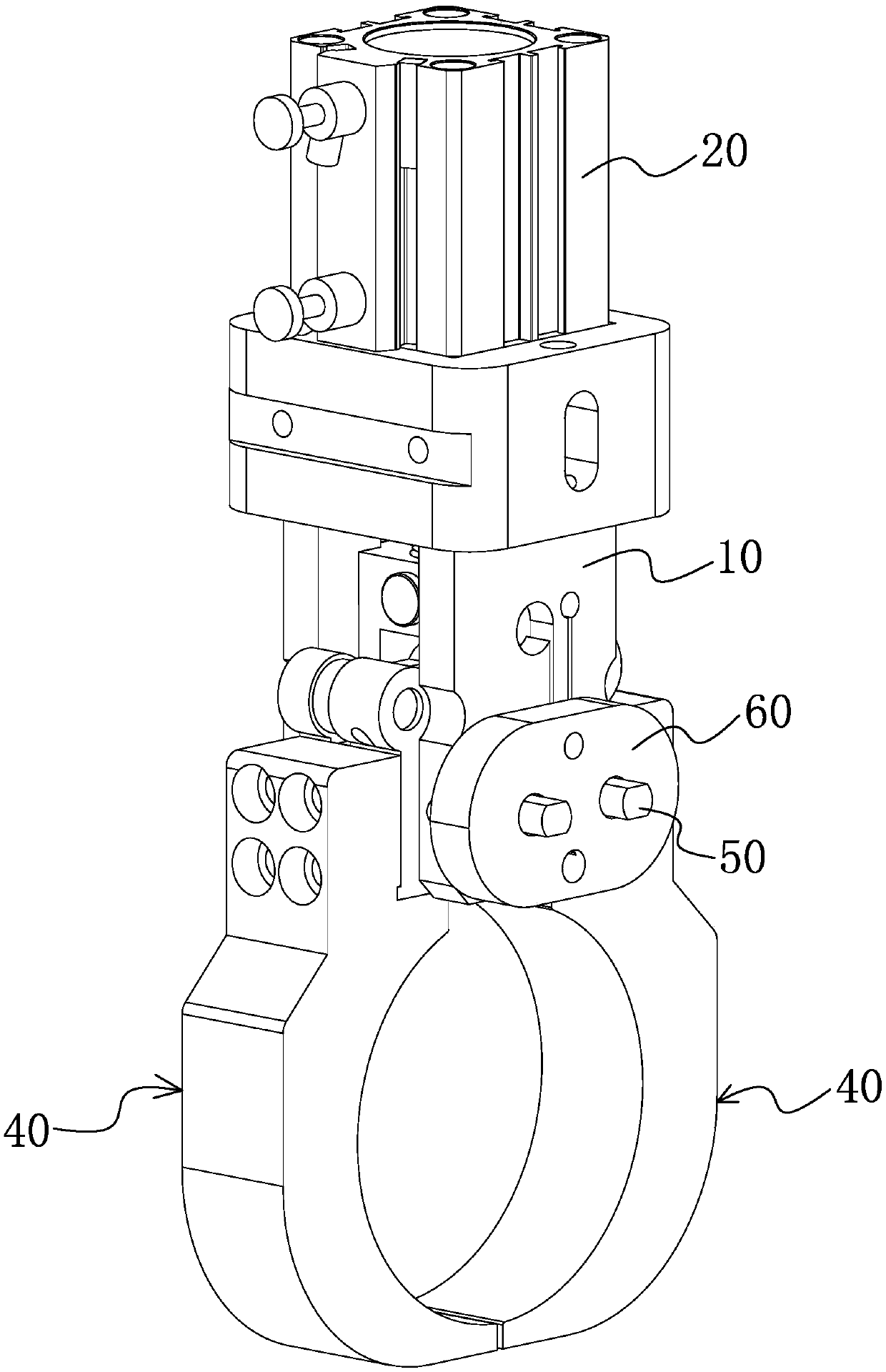
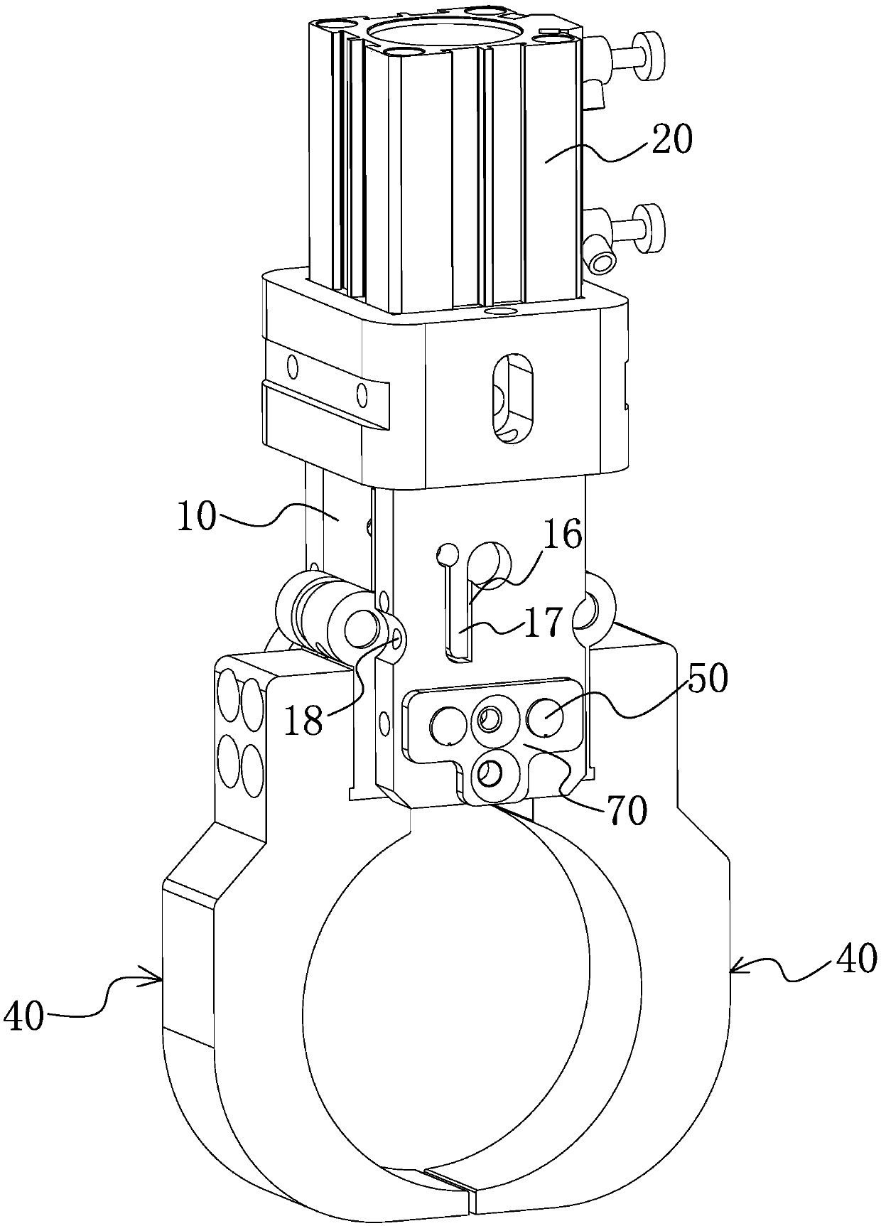
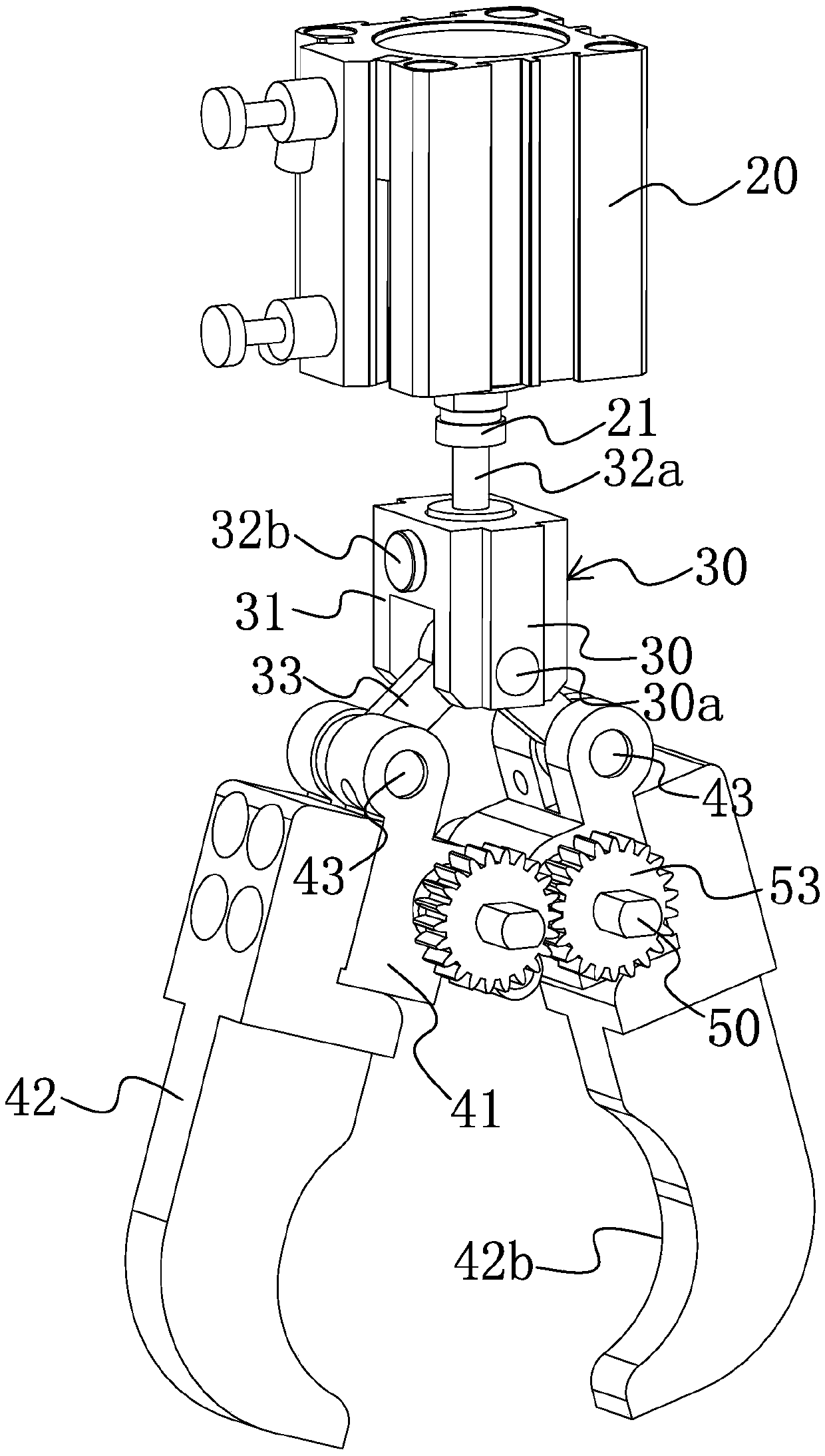
[0042] Such as Figure 1-Figure 4 As shown, a width-adjustable mechanical gripper device of the present invention includes a mounting base 10 , a driving member, a transmission member 30 , a gripper 40 and an eccentric shaft 50 .

[0043] The mounting base 10 is an inner hollow structure, and its bottom is provided with an assembly groove 11 that runs through the mounting base 10 transversely, and the driving member is fixedly connected with the top of the mounting base 10. Preferably, the driving member is a driving cylinder 20, and a piston rod 21 of the driving cylinder 20 Extending into the mounting base 10, the transmission part 30 is set in the mounting base 10 and connected with the driving part, there are two gripp...


PUM


Abstract

The invention provides a mechanical gripper with adjustable width and belongs to the technical field of mechanical grippers. The technical problems of high clamping failure rate and poor stability ofexisting gas claws are solved. The mechanical gripper with adjustable width comprises a mounting base, a driving member fixedly connected with the top of the mounting base, a transmission member arranged in the mounting base and connected with the driving member, two grippers symmetrically arranged at the bottom of the mounting base, and two eccentric shafts arranged in the mounting base, whereininner shafts of the eccentric shafts are movably connected with the mounting base; the two grippers extend into the mounting bases and are sleeved with outer shafts of the two eccentric shafts correspondingly; the two grippers are connected with the transmission member in a hinged mode; the two grippers are connected with the mounting base through the eccentric shafts; when the diameters of workpieces held by the gripper change, the width between the two grippers can be adjusted by adjusting the eccentric shafts, so that the gripper can grip the workpieces of different diameters without changing the driving stroke of the driving member, and thus the workpiece gripping accuracy of the whole gripper device is improved.

Description

technical field [0001] The invention belongs to the technical field of mechanical claws, and relates to a mechanical claw with adjustable width. Background technique [0002] Manipulator claws are commonly used mechanical parts in machining equipment at present, especially for the processing of shaft workpieces. Generally, different manipulator claws need to be designed according to different processing techniques and processing requirements. For the processing of shaft workpieces, common manipulators The jaws are two-jaw pneumatic grippers. [0003] For example, the invention patent application with the application number of 201711443883.3 discloses a pneumatic gripper, including a clamping seat, a cylinder and two claws are installed on the clamping seat, the cylinder is fixedly connected with the clamping seat, and the two claws are connected with the clamping seat. Hinged connection, the cylinder and the two claws are hingedly connected, driven by the cylinder, the two ...

Claims


Application Information

Patent Timeline
IPC IPC(8): B25J15/02B25J15/08
CPCB25J15/0206B25J15/0213B25J15/08
Inventor 杨云林
Owner 宁波开浦智能科技有限公司
Why Eureka
Try Eureka