
Paper processing and punching device

A punching device and paper technology, applied in the direction of metal processing, etc., can solve the problems of complicated paper punching operation, insufficient natural connection of paper, and inability to punch multiple sheets of paper, so as to prevent wrinkles, smooth punching operation, and avoid offset effect

Active Publication Date: 2019-04-19
SHAOXING UNIVERSITY
View PDF1 Cites 7 Cited by
  • Summary
  • Abstract
  • Description
  • Claims
  • Application Information

AI Technical Summary

Problems solved by technology

[0003] Chinese patent CN108858429A discloses a punching device for paper processing, including a fixed plate, a support frame, rollers and a sliding punching assembly, the left and right sides of the fixed plate are provided with support frames, and the lower end of the fixed plate is provided with a No. 1 motor. And the No. 1 motor is fixedly connected to the fixed plate through the No. 1 fixing frame, the left end of the No. 1 motor is connected to the No. 1 gear through the No. 1 rotating shaft, and the lower end of the No. 1 gear is engaged with the No. 2 gear, and the No. 2 gear is arranged on the No. 2 gear. In the middle part of the rotating shaft, the left and right ends of the No. 2 rotating shaft run through the support frame, and the No. 1 pulley is arranged at the left and right ends of the No. 2 rotating shaft; the left and right sides of the paper are fixed by the rollers and the fixing plate to prevent the paper from shifting; And by starting the No. 1 motor to drive the roller to rotate, so as to control the paper to move back and forth and determine the punching position in the front and rear directions; Position; in the above invention, the paper needs to be fixed by multi-party coordination before punching, which complicates the punching operation of the paper, and it is impossible to punch multiple sheets of paper together, and the connection between the punched paper and the paper that needs to be punched is not natural enough. It is easy to cause paper wrinkles when fixing the paper

Method used


Image

  • Paper processing and punching device
  • Paper processing and punching device
  • Paper processing and punching device

Examples


Embodiment Construction

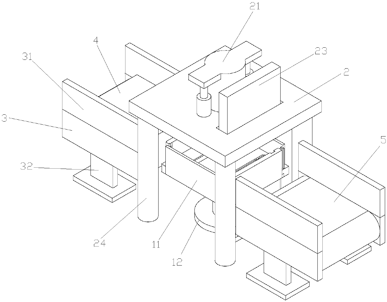
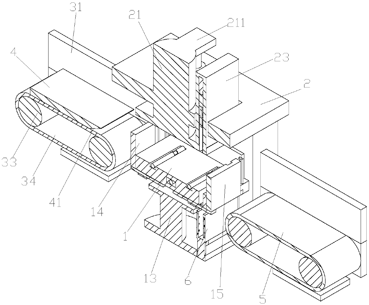
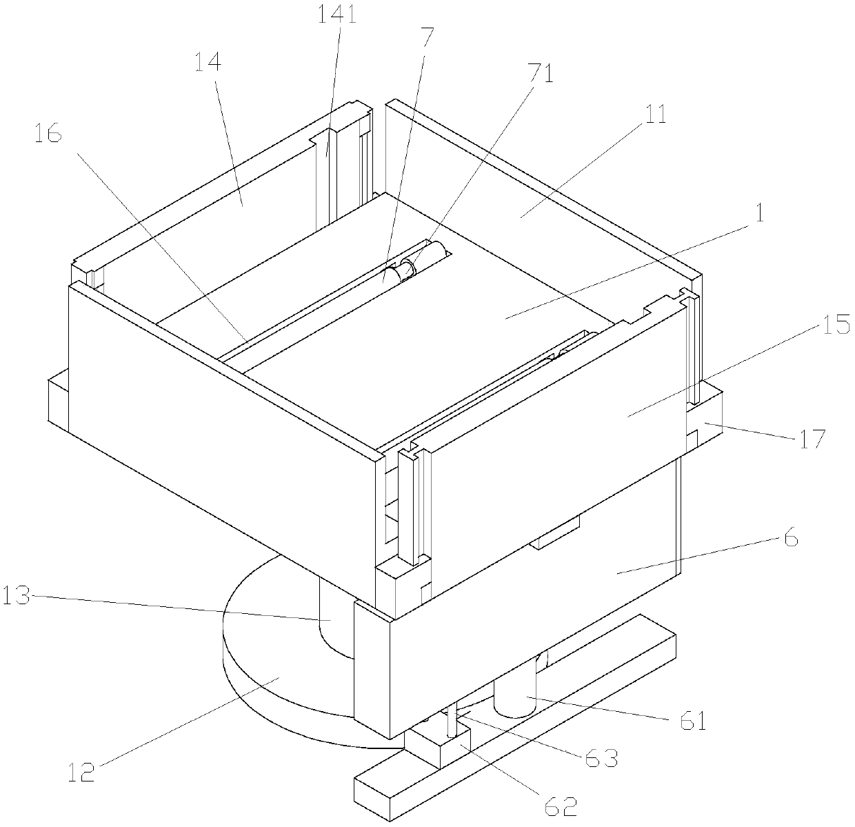
[0038] Such as Figure 1-22 As shown, a punching device for paper processing includes a first conveying device 3, a receiving platform 1 arranged on one side of the first conveying device 1, a punching device arranged above the receiving platform 1, and a The second conveying device 5 on the other side of the receiving platform 1, the first conveying device 3 includes a connecting frame, a first rotating roller 33 arranged on the connecting frame and sleeved on the first rotating roller 33 A conveyor belt 34, the conveyor belt 34 is provided with a tray 4 for placing paper, and the bottom surface of the tray near one side of the receiving platform is provided with a guide groove 41, so that the tray is convenient to enter into the receiving platform after moving to the receiving platform position; The top of the rack is provided with a fourth baffle 31, and the fourth baffles are respectively arranged on both sides of the conveyor belt. The fourth baffle acts as a limiter for ...


PUM


Abstract

The invention discloses a paper processing and punching device comprising a first conveyor device, a carrying table arranged on one side of the first conveyor device, a punching device arranged abovethe carrying table, and a second conveyor device arranged on the other side of the carrying table; the first conveyor device comprises a connecting frame, a first roller arranged on the connecting frame, and a conveyor belt arranged on the first roller in a sleeved manner; the conveyor belt is provided with a tray used for placing paper; the paper processing and punching device is characterized inthat the carrying table is provided with two first baffles, and the two first baffles are arranged on the both sides of the carrying table separately; and the carrying table is further provided witha second baffle and a third baffle which can do lifting motion along the side wall of the carrying table.

Description

technical field [0001] The invention belongs to the technical field of paper processing, and in particular relates to a paper processing punching device. Background technique [0002] Punching holes on paper is often required in copywriting work, such as binding documents, office paper, such as loose-leaf paper, cards, exam papers, etc., especially in the financial department, it is necessary to bind a large amount of paper. At present, due to the special nature of the work, the financial department will have a large number of reimbursement receipts, bills, etc. for binding, and for some more documents, the thickness is very thick, and it is difficult to bind with ordinary staplers, so it is necessary to use punching The machine punches holes in the paper before stapling. [0003] Chinese patent CN108858429A discloses a punching device for paper processing, including a fixed plate, a support frame, rollers and a sliding punching assembly, the left and right sides of the fix...

Claims


Application Information

Patent Timeline
IPC IPC(8): B26F1/02B26D7/01B26D7/06B26D7/02
CPCB26D7/015B26D7/025B26D7/0625B26F1/02
Inventor 何绍木张新华张苏敏王秀庆陈坤石松泉
Owner SHAOXING UNIVERSITY
Learn More