
Manipulator of bottle blowing machine

A technology of manipulators and bottle blowing machines, which is applied in the direction of manipulators, other household utensils, and household utensils. It can solve problems such as large limitations, poor stability, troubles, etc., and achieve the effects of tight clamping, wide application range, and improved stability.

Pending Publication Date: 2019-04-19
苏州普洽吹瓶科技有限公司
View PDF0 Cites 3 Cited by
  • Summary
  • Abstract
  • Description
  • Claims
  • Application Information

AI Technical Summary

Problems solved by technology

[0004] The purpose of the present invention is to provide a manipulator of a bottle blowing machine to solve the problem that the current grippers of one size can only correspond to preforms of one diameter. If the preforms with smaller diameters are clamped, It cannot be clamped and needs to be replaced, which has great limitations, and the operation is laborious and troublesome; the inclination angles of the threads of each bottle mouth are different, and it is often a problem of poor stability when clamping.

Method used


Image

  • Manipulator of bottle blowing machine
  • Manipulator of bottle blowing machine
  • Manipulator of bottle blowing machine

Examples


Embodiment Construction

[0018] The following will clearly and completely describe the technical solutions in the embodiments of the present invention with reference to the accompanying drawings in the embodiments of the present invention. Obviously, the described embodiments are only some, not all, embodiments of the present invention. Based on the embodiments of the present invention, all other embodiments obtained by persons of ordinary skill in the art without making creative efforts belong to the protection scope of the present invention.

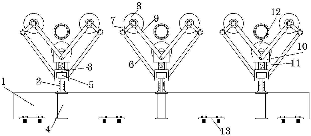
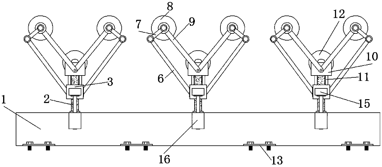
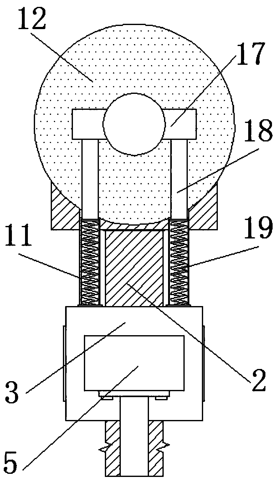
[0019] see Figure 1-6 , the present invention provides a technical solution: a manipulator of a bottle blowing machine, including a fixed seat 1, the top of the fixed seat 1 is welded with a fixed column 2, three fixed columns 2 are welded, and the three fixed columns 2 are arranged at equal intervals The top of the fixed seat 1 and the outer wall of the fixed column 2 are provided with a slider 3, the slider 3 is slidably connected with the fixed column 2, a...


PUM


Abstract

The invention discloses a manipulator of a bottle blowing machine. The manipulator comprises a fixed base, wherein three fixed columns are welded at the top end of the fixed base, the three fixed columns are arranged at the top end of the fixed base at equal intervals, and each fixed column is sleeved with a sliding block. The manipulator of the bottle blowing machine can be installed on a linearguide rail type mechanical arm through the fixed base, a bottle preform is clamped and fed with the movement and positioning of the mechanical arm, the sliding blocks can be pushed through piston rodsby starting air cylinders, the sliding blocks drive fixed rod pieces to conduct linear movement, meanwhile swing rod pieces keep swinging close to the fixed rod pieces and drive rotating rod pieces to rotate around the hinge points on fixed blocks, and thus two clamping wheels are close to each other. At the same time, because of feeding of the sliding blocks, push wheels also move and get closeto the clamping wheels, forming a triangle to clamp the bottle preform in three directions, and therefore the manipulator can be adapted to bottle preforms with different opening diameters, and the application range is wider.

Description

technical field [0001] The invention relates to the technical field of bottle blowing machines, in particular to a robot for bottle blowing machines. Background technique [0002] The bottle blowing machine is a machine that can blow plastic particles or preforms into bottles through certain technological means. At present, most of them use linear guide-type robotic arms to clamp the preforms from the heating area and send them to the mold. The forming area realizes automatic loading, but as far as the clamping manipulator on the mechanical arm is concerned, there are still some shortcomings in the process of use. [0003] Most of the current manipulators have a gripper structure. Through a certain number of linkage mechanisms, the outer diameter of the preform can be clamped. However, under normal circumstances, a gripper of one size can only correspond to a preform of one diameter. If the preform with a small diameter is clamped, it cannot be clamped and needs to be repla...

Claims


Application Information

Patent Timeline
IPC IPC(8): B29C49/42B29C31/08B25J15/00B29L22/00B29L31/00
CPCB25J15/00B29C31/08B29C49/4205B29L2022/00B29L2031/7158Y02P40/57
Inventor 夏文波汪木兰
Owner 苏州普洽吹瓶科技有限公司
Learn More