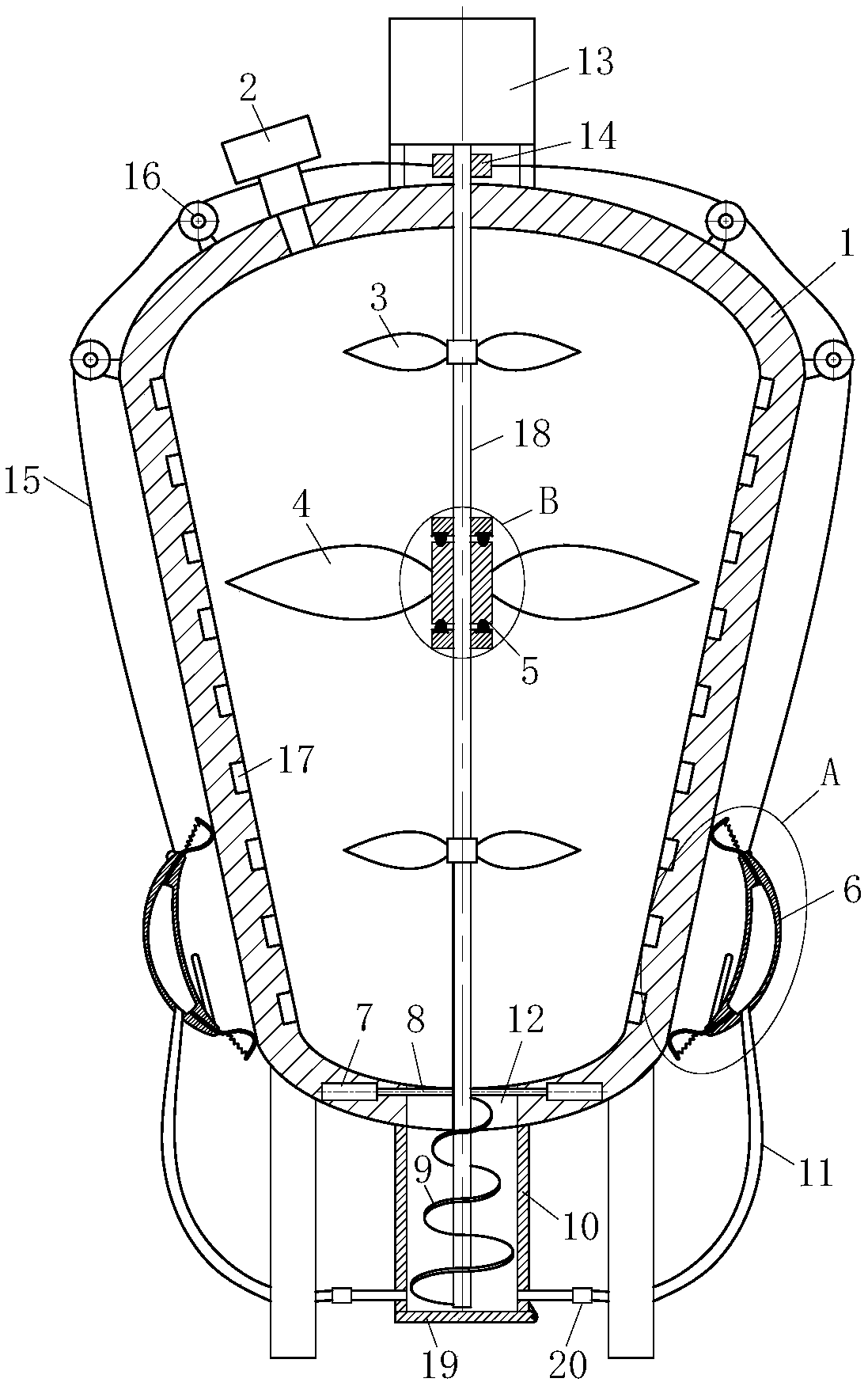
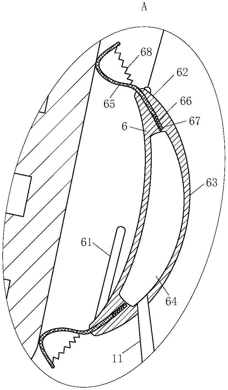
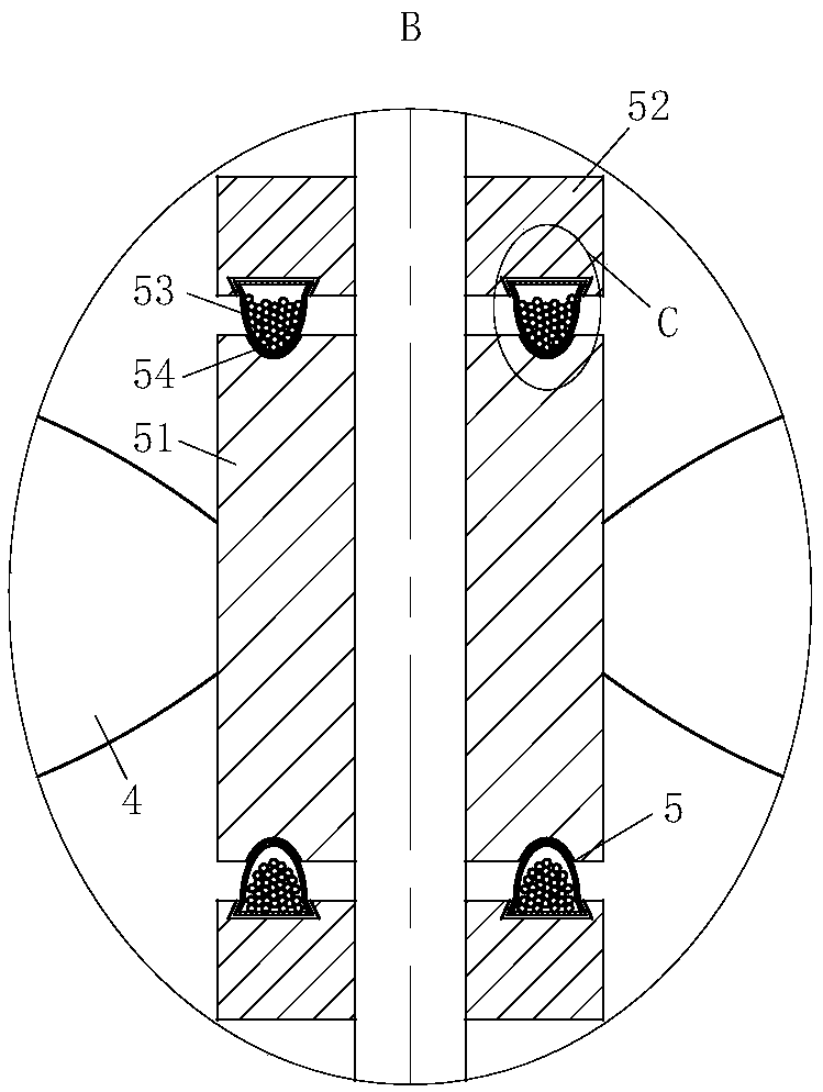
[0019] use Figure 1-Figure 4 An automatic temperature-regulating bioengineering reactor according to an embodiment of the present invention will be described as follows.
[0020] Such as figure 1 As shown, an automatic temperature-regulating bioengineering reactor according to the present invention includes a reactor 1, a feed port 2, a heat conduction module 6 and a feed port 12. The top of the reactor 1 is provided with a feed Port 2, the top of the reactor 1 is connected to the motor 13 through the support frame, the output shaft of the motor 13 is connected with a rotating rod 18, one end of the rotating rod 18 extends to the inside of the reactor 1, and the outer top and bottom ends of the rotating rod 18 A first blade 3 is provided at each location, and a second blade 4 is provided on the outside of the rotating rod 18 in the middle of the two first blades 3. The diameter of the second blade 4 is larger than the diameter of the first blade 3 The outside of the rotating rod 18 is fixedly connected with a fixed tube 14, which is located outside the reactor 1, and the outside of the reactor 1 is equiangularly provided with four sets of rollers 16, each of which has two rollers. 1 is provided with a heat conduction module 6, one end of the fixed pipe 14 is fixed with a plurality of rigid ropes 15 at an equal angle, and the other end of the rigid rope 15 passes through two rollers 16 and is fixed to the heat conduction module 6. The heat conduction module 6 is used for The heat conduction module 6 includes a heat conduction member 62 and a radiation mirror 61. The heat conduction member 62 surrounds the outside of the reactor 1, and the radiation mirror 61 is fixedly connected to the inside of the heat conduction member 62; the reaction kettle 1 The bottom of the reactor is provided with a discharge port 12; the inner surface of the reactor 1 is equipped with a plurality of temperature sensors 17 equidistantly, and the outside of the reactor 1 is provided with a controller, and the controller is used to control the motor 13 and the temperature sensor 17 jobs.
[0021] When working, the reaction liquid is introduced into the reactor 1 from the feed port 2. When the temperature sensor 17 senses that the interior of the reactor 1 is unevenly heated, the temperature sensor 17 transmits the signal to the controller. The motor 13 is controlled to work, and the motor 13 drives the rotating rod 18 to rotate, thereby driving the fixed tube 14 to rotate. Since the fixed tube 14 is connected to the heat conduction module 6 through a rigid rope 15, when the fixed tube 14 rotates, the rigid rope 15 is tightened and wound around On the fixed pipe 14, the rigid rope 15 moves on the roller 16 and drives the thermal conduction module 6 to move upward to the part of the reactor 1 where the temperature is lower than the temperature of other positions on the reactor 1. The thermal conduction member 62 generates heat and acts on the radiation mirror 61 When the heat conduction module 6 needs to move upward, the motor 13 rotates in the opposite direction to loosen the rigid rope 15 and the rigid rope 15 No upward pulling force is applied to the heat conduction module 6, and the heat conduction module 6 moves downward under its own gravity to heat other parts of the reactor 1, which can not only adjust the temperature on the reactor 1, but also ensure the reactor 1 The whole body is heated uniformly, so that the temperature on the reactor 1 is the same, and the accuracy of the bioengineering reaction is improved. At the same time, during the rotation of the motor 13, the rotating rod 18 rotates to drive the first blade 3 and the second blade 4 to rotate, thereby The reaction liquid inside the reactor 1 is stirred to further improve the uniformity of the reaction liquid heating. When the reaction is completed, the reaction liquid is led out from the discharge port 12 to complete the reaction.
[0022] Such as Figure 1-Figure 2 As shown, the heat-conducting member 62 is provided with a first cavity 55 inside, the bottom of the reactor 1 is located below the discharge port 12, and a transition frame 10 is fixedly connected to the bottom of the transition frame 10, which is rotatably connected with a discharge door 19. The rotating rod 18 extends to the inside of the transition frame 10. The outside of the rotating rod 18 is provided with an auger 9, which is located inside the transition frame 10. The discharge port 12 is provided with a symmetrical sealing plate 8 to seal The plate 8 is driven by the hydraulic cylinder 7, the outside of the transition frame 10 is connected with the first cavity 55 through a plurality of air ducts 11 at equal angles, and the air duct 11 is provided with a control valve 20. When the heat conduction module 6 is adjusted downwards, the hydraulic cylinder 7 drives the sealing plate 8 to seal the discharge port 12, and the rotating rod 18 rotates to drive the screw 9 to rotate. After the screw 9 rotates, negative pressure is generated in the transition cavity. The control valve 20 is opened, and the gas inside the transition frame 10 enters the inside of the second cavity 64 through the air duct 11, so that the heat conduction module 6 has a downward movement trend, thereby helping the heat conduction module 6 to move downward. When feeding, the hydraulic cylinder 7 shrinks, driving the sealing plate 8 to open, and the reaction liquid enters the interior of the transition frame 10. At this time, the control valve 20 is closed, and the rotating rod 18 rotates to drive the auger 9 to rotate. The auger 9 can play the role of feeding. Open the discharging door 19 on the transition frame 10, and the reaction liquid can be led out.
[0023] Such as image 3 As shown, the second blade 4 is connected to the rotating rod 18 through a buffer module 5. The buffer module 5 includes a fixed seat 51, a connecting seat 52, a rubber bump 53 and a recess 54. The fixed seat 51 and the connecting seat 52 are respectively provided On the outside of the rotating rod 18, the number of the connecting seats 52 is two, the two connecting seats 52 are symmetrical about the horizontal center line of the fixing seat 51, the lower connecting seat 52 is fixedly connected to the rotating rod 18, and the fixing seat 51 is sleeved with the upper connecting seat 52 Connected to the outside of the rotating rod 18, the second paddle 4 is fixedly connected to the outside of the fixing base 51, the inner side wall of the connecting base 52 is provided with a plurality of rubber bumps 53 at equal angles, and both ends of the fixing base 51 are provided with a plurality of equal angles. The volume of the rubber bump 53 is greater than the volume of the recess 54. When the rotating rod 18 just starts to rotate, since the rotating rod 18 is connected to the rotating rod 18 through the buffer module 5, the buffer module 5 can play a certain buffering effect, so that after the rotating rod 18 suddenly starts, the second blade 4 will not The rotating rod 18 is broken due to its own weight, which protects the rotating rod 18. When the rotating rod 18 starts to start, the rotating rod 18 drives the lower connecting seat 52 to rotate, and the rubber bumps 53 are on both ends of the fixed seat 51 Sliding, through the action of friction, drives the second paddle 4 to slowly rotate. When the second paddle 4 slowly rotates to the same speed as the rotating rod 18, the rubber bump 53 is just locked in the inside of the recess 54. The rotation of the second blade 4 is realized, thereby ensuring the stability when the second blade 4 and the rotating rod 18 rotate at the same speed.
[0024] Such as figure 2 As shown, the heat conducting member 62 includes a surrounding member 63 and a rubber ring 65. Two ends of the surrounding member 63 are respectively connected to the rubber ring 65 by springs. Both ends of the surrounding member 63 are provided with grooves 67, and the first spring 66 is located in the groove. Inside 67, one end of the rubber ring 65 extends to the inside of the groove 67. The cross section of the rubber ring 65 is a hook-shaped structure with one end bent away from the reaction vessel 1, and a second spring 68 is provided on the rubber ring 65. When the heat-conducting member 62 moves up and down, the rubber ring 65 is connected to the reactor 1, making the heat-conducting member 62 more adaptable to the reactor 1 during the up-and-down movement, thereby improving the sealing effect of the heat-conducting module 6. Under the elastic action of the spring 66 and the second spring 68, the adaptability of the rubber ring 65 is enhanced, which is more conducive to the movement of the heat conducting member 62.
[0025] Such as Figure 4 As shown, one end of the rubber bump 53 is engaged with the inside of the connecting block, the cross section of the rubber bump 53 is set as a combination of an inverted trapezoidal structure and a semi-elliptical shape, and a second cavity is opened inside the rubber bump 53 Cavities 64. Since the rubber bump 53 is provided with a second cavity 64 inside, the degree of deformation of the rubber bump 53 is increased, so that the rubber bump 53 can be more smoothly rotated on the surface of the connecting seat 52, preventing the rubber bump 53 from being The internal clamping of the pit 54 is too tight, which affects the cushioning effect, and the second cavity 64 is provided with rubber balls and steel balls, which can simultaneously ensure the rigidity and flexibility of the rubber bump 53 and improve the rubber bump The adaptability of 53 is beneficial to drive the rotation of the second blade 4.
[0026] Such as figure 1 As shown, the outer diameter of the auger 9 increases sequentially from top to bottom. When feeding, because the outer diameter of the auger 9 increases from top to bottom, the top of the auger 9 will not block the reaction liquid when the reaction liquid just starts to be fed, thereby ensuring normal feeding and the auger 9 The contact area with the transition frame 10 is reduced, which reduces the wear between the auger 9 and the transition frame 10, which is beneficial to the rotation of the auger 9 and protects the auger 9 and the transition frame 10, and extends the auger 9 and the transition frame 10. The service life of dragon 9 and transition box 10.
[0027] The specific workflow is as follows:
[0028] When working, the reaction liquid is introduced into the reactor 1 from the feed port 2. When the temperature sensor 17 senses that the interior of the reactor 1 is unevenly heated, the temperature sensor 17 transmits the signal to the controller. The motor 13 is controlled to work, and the motor 13 drives the rotating rod 18 to rotate, thereby driving the fixed tube 14 to rotate. Since the fixed tube 14 is connected to the heat conduction module 6 through a rigid rope 15, when the fixed tube 14 rotates, the rigid rope 15 is tightened and wound around On the fixed pipe 14, the rigid rope 15 moves on the roller 16 and drives the thermal conduction module 6 to move upward to the part of the reactor 1 where the temperature is lower than the temperature of other positions on the reactor 1. The thermal conduction member 62 generates heat and acts on the radiation mirror 61 When the heat conduction module 6 needs to move upward, the motor 13 rotates in the opposite direction to loosen the rigid rope 15 and the rigid rope 15 No upward pulling force is applied to the heat conduction module 6, and the heat conduction module 6 moves downward under its own gravity to heat other parts of the reactor 1, which can not only adjust the temperature on the reactor 1, but also ensure the reactor 1 The whole body is heated uniformly, so that the temperature on the reactor 1 is the same, and the accuracy of the bioengineering reaction is improved. At the same time, during the rotation of the motor 13, the rotating rod 18 rotates to drive the first blade 3 and the second blade 4 to rotate, thereby The reaction liquid inside the reactor 1 is stirred to further improve the uniformity of the reaction liquid heating. When the reaction is completed, the reaction liquid is led out from the discharge port 12 to complete the reaction.