
Sley system for high-speed rapier loom

A rapier loom and reed technology, applied in looms, textiles, textiles and papermaking, etc., can solve the problems of restricting the weaving quality and weaving efficiency of fabrics, cumbersome installation, arousing strong vibration and noise, etc., so as to improve the fabric quality. Weaving quality and weaving efficiency, meeting compression requirements, the effect of reducing the deformation of the sled

Pending Publication Date: 2019-04-19
TIANJIN POLYTECHNIC UNIV
View PDF0 Cites 0 Cited by
  • Summary
  • Abstract
  • Description
  • Claims
  • Application Information

AI Technical Summary

Problems solved by technology

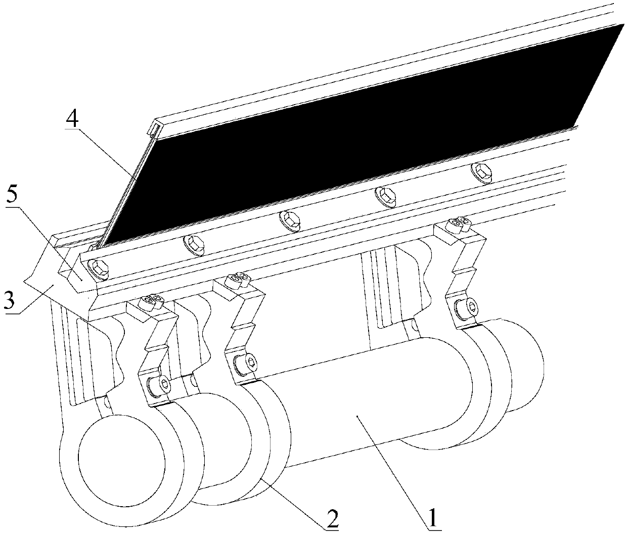
figure 1 It is the sley system used by Zhejiang Wanli Textile Machinery Co., Ltd. on high-speed rapier looms. This sley system only relies on the set screw on the sley foot 2 to force the sley foot and the swing shaft to rely on frictional fixed connection, which is difficult to fully guarantee During the movement of the rapier loom, there is no turning and axial sliding. The sley 3 is pressed on the sley foot 2 through a small bead 5 with a screw on one side. When the loom is running at high speed, the pressure surface is narrow , so the safety factor is not high, there are many assembly parts in the whole system, and the installation is cumbersome. The sley 3 and the bead 5 are solid parts, which are inconvenient to disassemble. Moreover, when the cam mechanism is running at high speed, the inertial force of the follower in the system increases sharply. The induced component deformation will cause the movement law of the working end to deviate from the predetermined requirement, resulting in a dynamic movement deviation that cannot be ignored, and even arouse strong vibration and noise, thereby restricting the quality and efficiency of fabric weaving

Method used


Image

  • Sley system for high-speed rapier loom
  • Sley system for high-speed rapier loom
  • Sley system for high-speed rapier loom

Examples


Embodiment Construction

[0022] The technical solutions of the present invention will be described in detail below in conjunction with the accompanying drawings and specific embodiments.

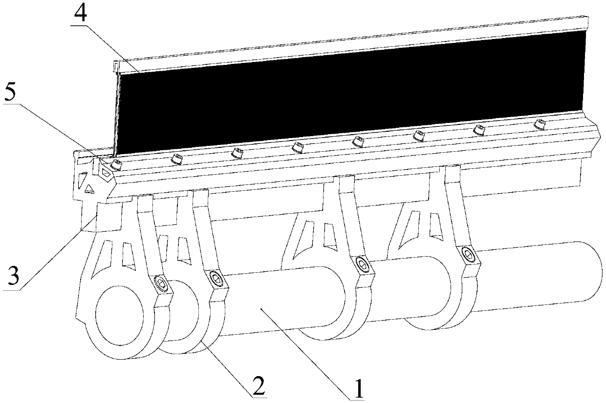
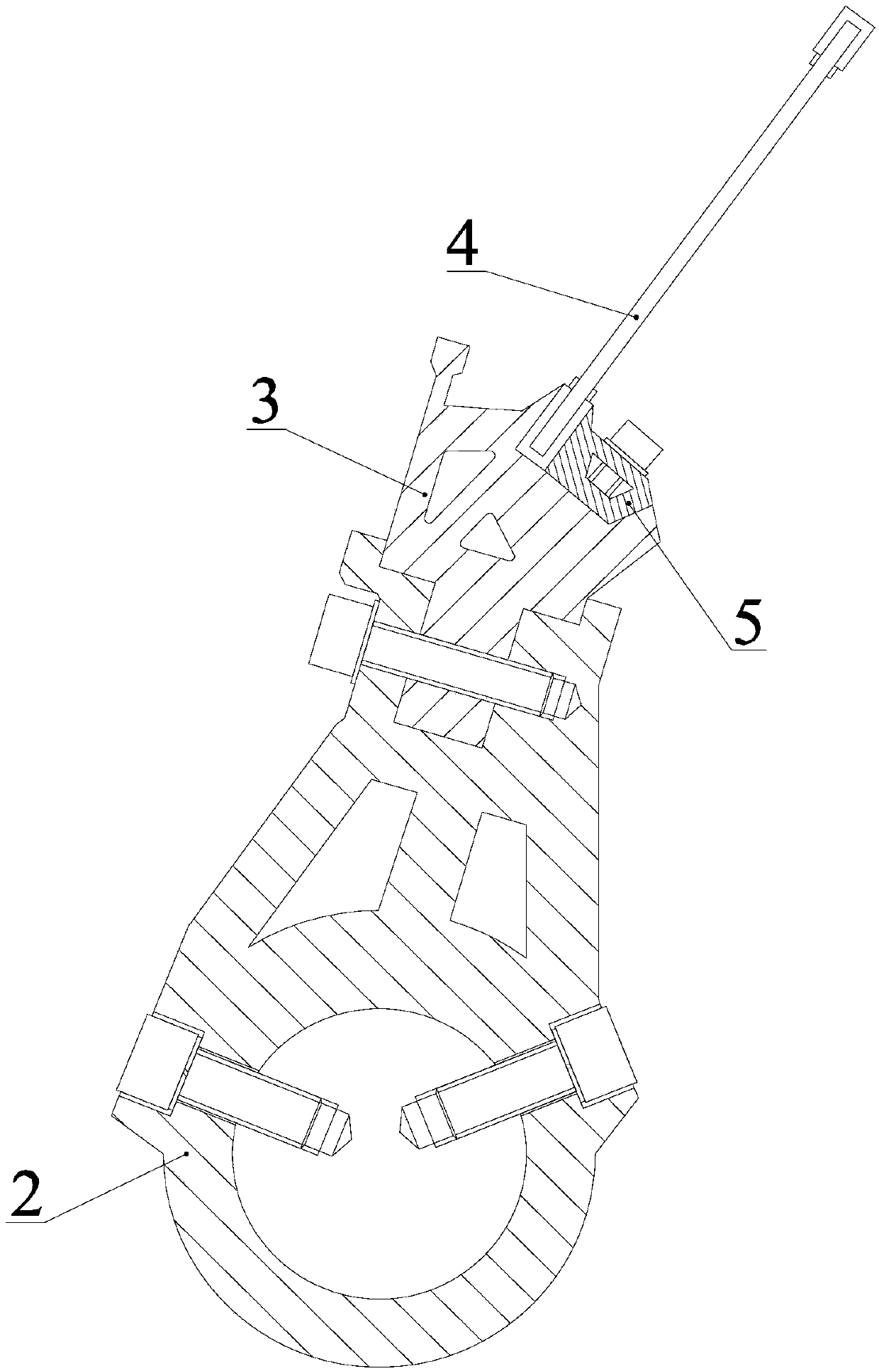
[0023] A sley system applied to a high-speed rapier loom, used for connecting a swing shaft 1 and a steel buckle 4, including a sley 3 and a plurality of sley feet 2;

[0024] The outer contour of the longitudinal section of the sley foot 2 is in the shape of a drop or a drop-like shape as a whole, with a through hole on the lower side and a support frame on the upper side; at least two screw holes are provided on the side of the through hole position; preferably, The positions of the screw holes provided on the side walls of the through hole positions of a plurality of sley feet are all the same; as a specific embodiment of the present invention, as Figure 2-4 As shown, two screw holes are provided on the side walls of the through holes of the plurality of sley feet 2, which are respectively symmetrically arranged...


PUM


Abstract

The invention discloses a sley system for a high-speed rapier loom. The sley system is used for connecting a swing shaft with a steel buckle and comprises a sley and a plurality of sley swords, the outer contour lines of the longitudinal sections of the sley swords are integrally in water drop shapes or shapes similar to water drops, through holes are formed in the lower sides of the sley swords,supporting frames are arranged on the upper sides of the sley swords, at least two screw holes are formed in the side faces of the through holes, the swing shaft penetrates the through holes in the sley swords and is jacked and fixed by screws and the screw holes, openings are formed in the tops of the supporting frames and in symmetric two-layer step shapes, a groove is formed in the upper side of the sley, the steel buckle is fixed into the groove by a trim strip, two layers of projections are arranged on the lower side of the sley, the shapes of the projections are matched with those of thetop openings of the supporting frames of the sley swords, the projections of the sley are inserted into the tops of the supporting frames of the sley swords, and the screws penetrate the sley and thesley swords to fix the sley and the sley swords. According to the sley system, turning and axial sliding of the sley swords in the use process can be avoided, the sley is low in stress and difficultly deforms, and the sley system is less in vibration and low in noise when in use.

Description

technical field [0001] The invention relates to the field of textile machinery, in particular to a sley system applied to a high-speed rapier loom. Background technique [0002] The sley system of domestic high-speed rapier looms has few types and a single structure, and is in the stage of exploration and exploration. figure 1 It is the sley system used by Zhejiang Wanli Textile Machinery Co., Ltd. on high-speed rapier looms. This sley system only relies on the set screw on the sley foot 2 to force the sley foot and the swing shaft to rely on frictional fixed connection, which is difficult to fully guarantee During the movement of the rapier loom, there is no turning and axial sliding. The sley 3 is pressed on the sley foot 2 through a small bead 5 with a screw on one side. When the loom is running at high speed, the pressure surface is narrow , so the safety factor is not high, there are many assembly parts in the whole system, and the installation is cumbersome. The sley ...

Claims


Application Information

Patent Timeline
Patent Type & Authority Applications(China)
IPC IPC(8): D03D49/60
CPCD03D49/60
Inventor 魏展金国光路春辉畅博彦李丹丹宋艳艳魏晓勇
Owner TIANJIN POLYTECHNIC UNIV
Learn More