
Method and system for determining position of ground shallow shaft micro-seismic monitoring observation station

A determination method and observation station technology, applied in the field of petroleum geophysical exploration, can solve the problems of small attenuation of microseismic signals, limited monitoring range, strong microseismic signals, etc., and achieve the effect of reducing noise impact, reducing monitoring cost, and strong energy

Active Publication Date: 2019-04-19
CHINA PETROLEUM & CHEM CORP +1
View PDF7 Cites 6 Cited by
  • Summary
  • Abstract
  • Description
  • Claims
  • Application Information

AI Technical Summary

Problems solved by technology

[0003] In-hole monitoring method: the geophone is located in the downhole, close to the fracturing fracture, the micro-seismic signal attenuation is small, the received micro-seismic signal is strong, the environmental noise interference is small, and the signal-to-noise ratio is high, but there are some limitations, such as downhole observation It is required that the geophone can adapt to the harsh environment underground, has high requirements for equipment, high cost, limited monitoring range, and is not suitable for permanent monitoring, etc.

Method used


Image

  • Method and system for determining position of ground shallow shaft micro-seismic monitoring observation station
  • Method and system for determining position of ground shallow shaft micro-seismic monitoring observation station
  • Method and system for determining position of ground shallow shaft micro-seismic monitoring observation station

Examples


Embodiment Construction

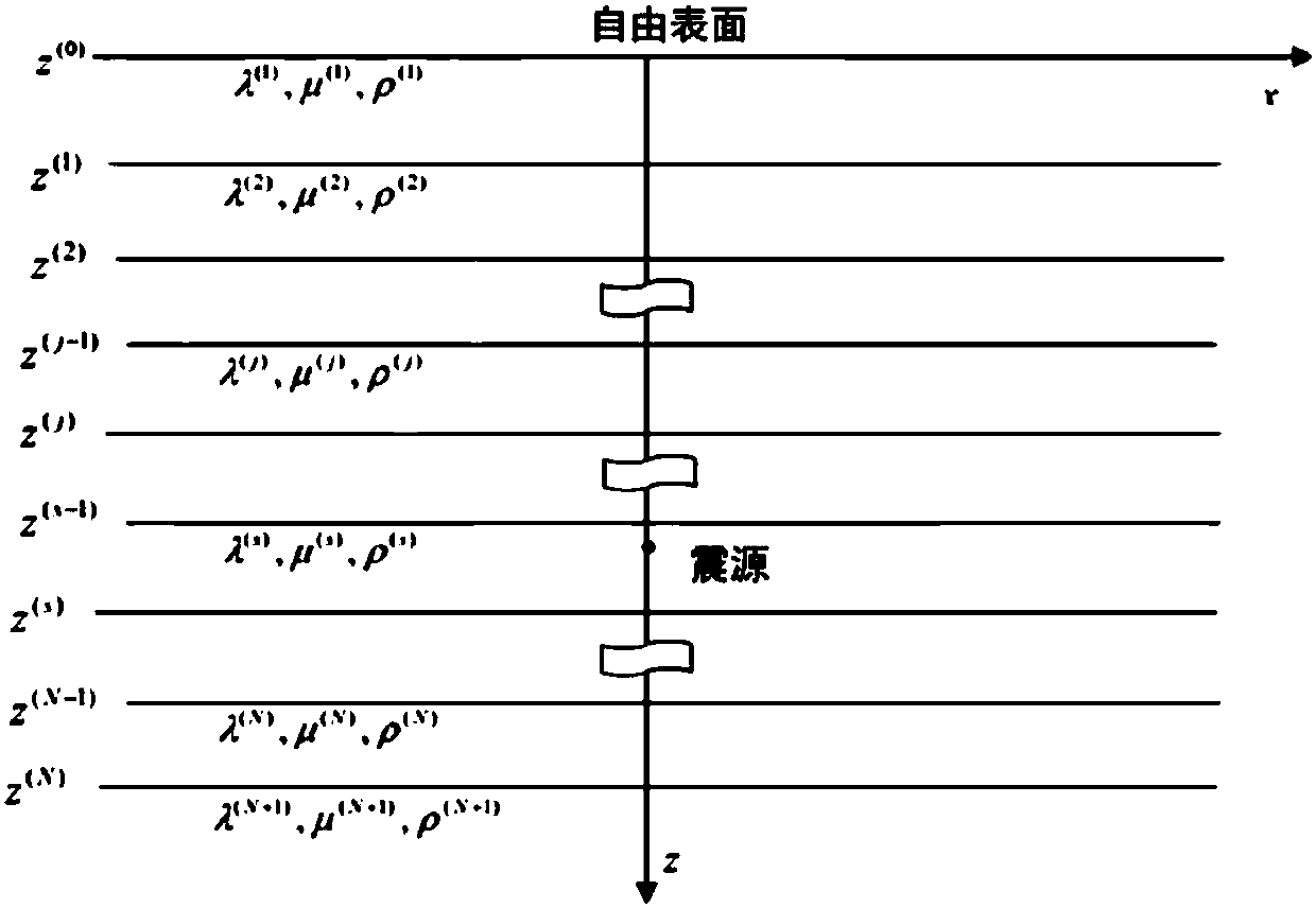
[0036] The present invention will be described in more detail below with reference to the accompanying drawings. Although preferred embodiments of the invention are shown in the drawings, it should be understood that the invention may be embodied in various forms and should not be limited to the embodiments set forth herein. Rather, these embodiments are provided so that this disclosure will be thorough and complete, and will fully convey the scope of the invention to those skilled in the art.

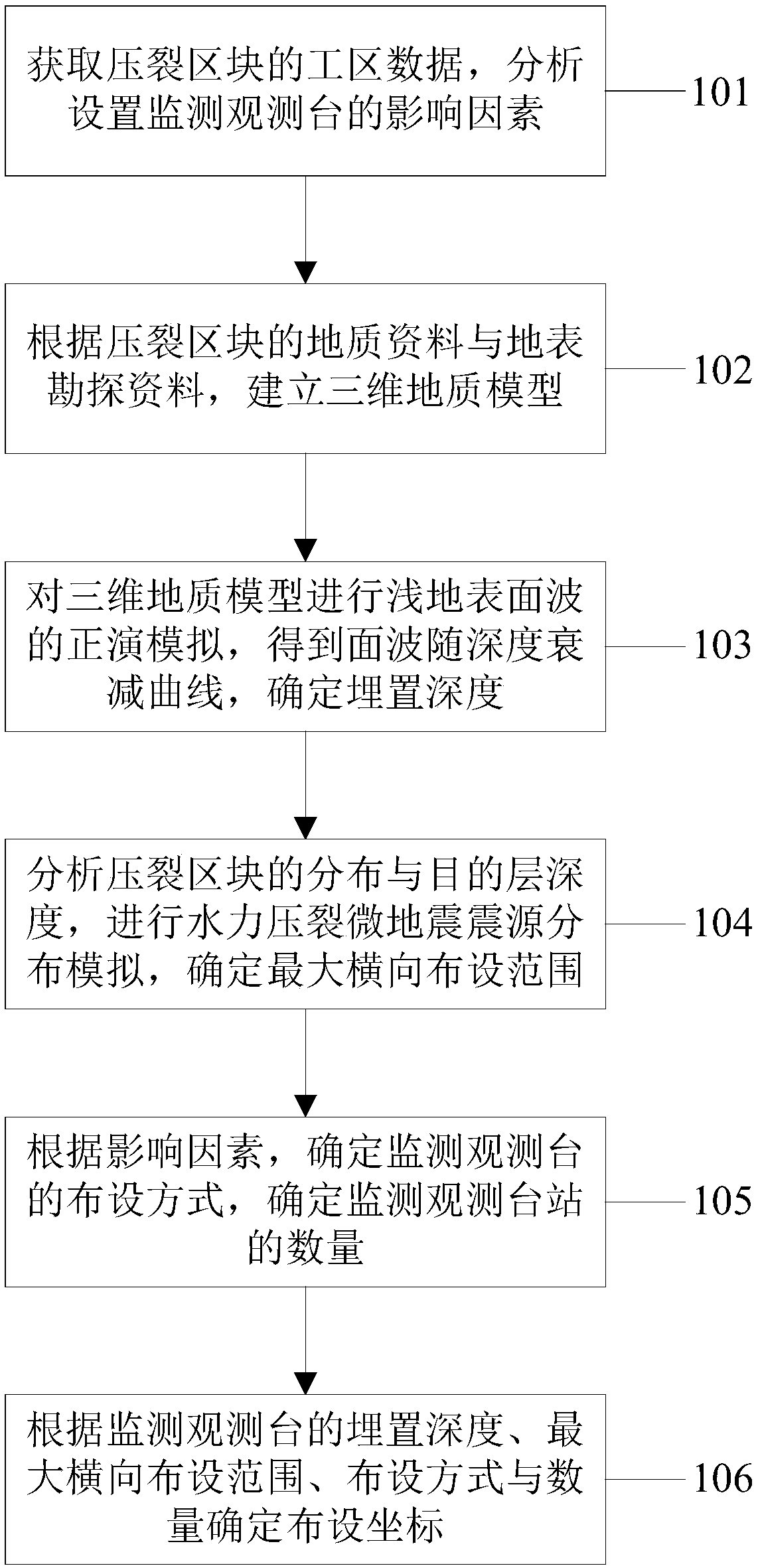
[0037] figure 1 A flow chart showing the steps of the method for determining the position of a surface shallow well microseismic monitoring and observation station according to the present invention.

[0038]In this embodiment, the method for determining the position of the ground shallow well microseismic monitoring observation station according to the present invention may include: Step 101, obtaining the work area data of the fracturing block, and analyzing the influencing factors ...


PUM


Abstract

The invention discloses a method and system for determining the position of a ground shallow shaft micro-seismic monitoring observation station. The method comprises the steps that the work area dataof a fracturing block are acquired, and the influencing factors of monitoring observation station setting are analyzed; a three-dimensional geological model is established according to the geologicaldata of the fracturing block and surface exploration data; shallow surface wave forward modeling is carried out the three-dimensional geological model to acquire a surface wave attenuation curve withdepth and determine the embedding depth; the fracturing block distribution and the depth of a target layer are analyzed, and hydraulic fracturing micro-seismic origin distribution simulating is carried out to determine the maximum horizontal layout range; according to the influencing factors, the layout mode of the monitoring observation station is determined, and the number of the monitoring observation station is determined; and the layout coordinate is determined according to the embedding depth, the maximum horizontal layout range, the layout mode and the number of the monitoring observation station. According to the invention, the collection cost can be reduced; the amount of seismic record data is reduced; the calculation efficiency is accelerated; and the method and system have certain advantages in the stage of multi-well long-term monitoring and development zone.

Description

technical field [0001] The invention relates to the field of petroleum geophysical exploration, and more specifically, to a method and system for determining the position of a surface shallow well microseismic monitoring and observation station. Background technique [0002] Microseismic fracturing monitoring technology has now become a commonly used monitoring technology in the development of oil and gas fields in tight reservoirs. At this stage, it is mainly based on well monitoring and surface monitoring. [0003] In-hole monitoring method: the geophone is located in the downhole, close to the fracturing fracture, the micro-seismic signal attenuation is small, the received micro-seismic signal is strong, the environmental noise interference is small, and the signal-to-noise ratio is high, but there are some limitations, such as downhole observation It is required that the geophone can adapt to the harsh environment underground, has high requirements for equipment, high co...

Claims


Application Information

Patent Timeline
IPC IPC(8): G01V1/42
CPCG01V1/42
Inventor 王瑜程磊磊李宏郭全仕
Owner CHINA PETROLEUM & CHEM CORP
Learn More