DC relay capable of arc extinguishing and resisting short-circuit current
A DC relay, anti-short-circuit technology, applied in electromagnetic relays, electromagnetic relay details, relays, etc., can solve the problems that the contact pressure is not enough to resist the electric repulsion of the moving spring, the volume is small, and the suction force cannot be provided, and the magnetic efficiency is achieved. High, the magnetic circuit is not easy to saturate the effect
- Summary
- Abstract
- Description
- Claims
- Application Information
AI Technical Summary
Problems solved by technology
Method used
Image

Examples
Embodiment 1
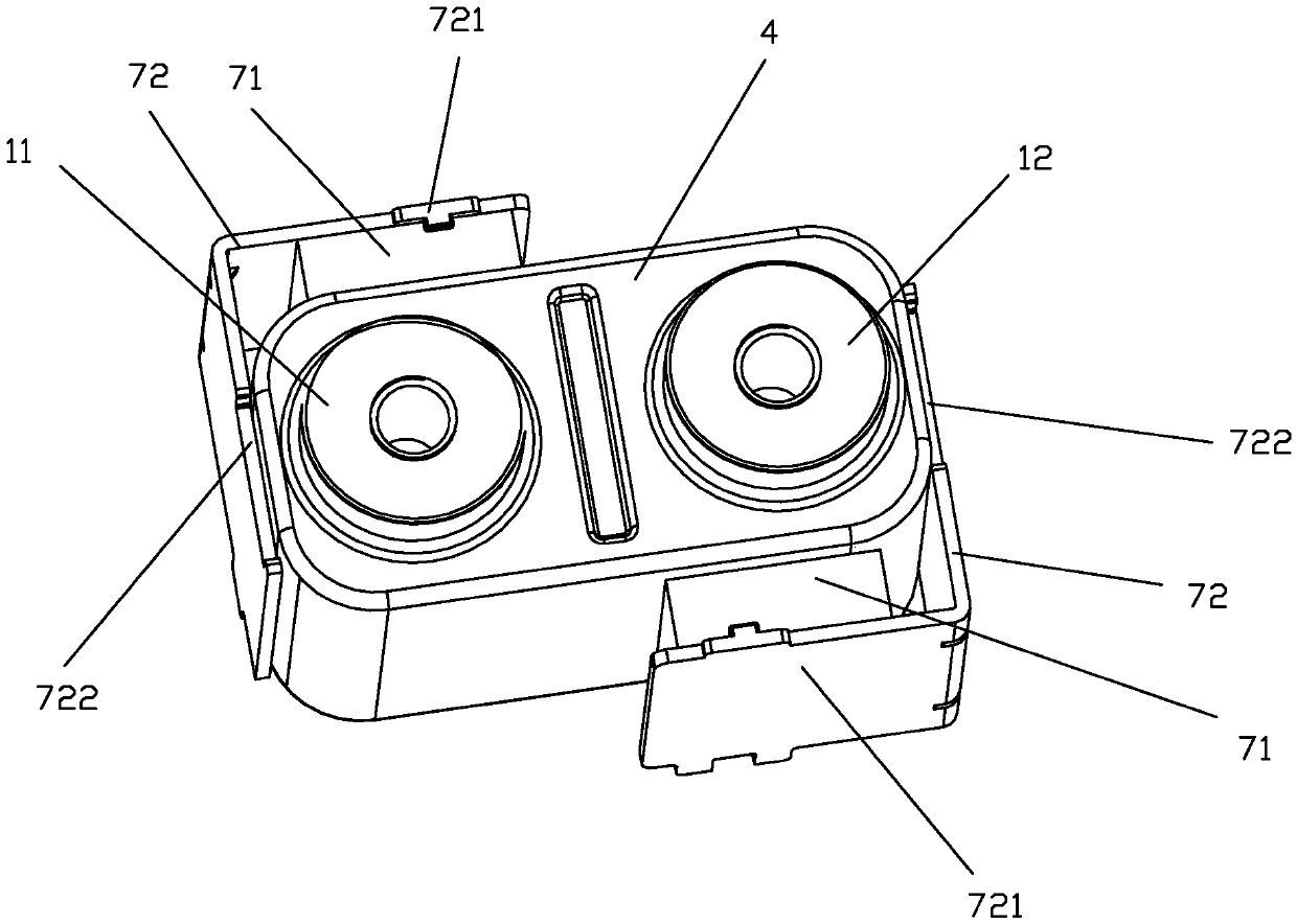
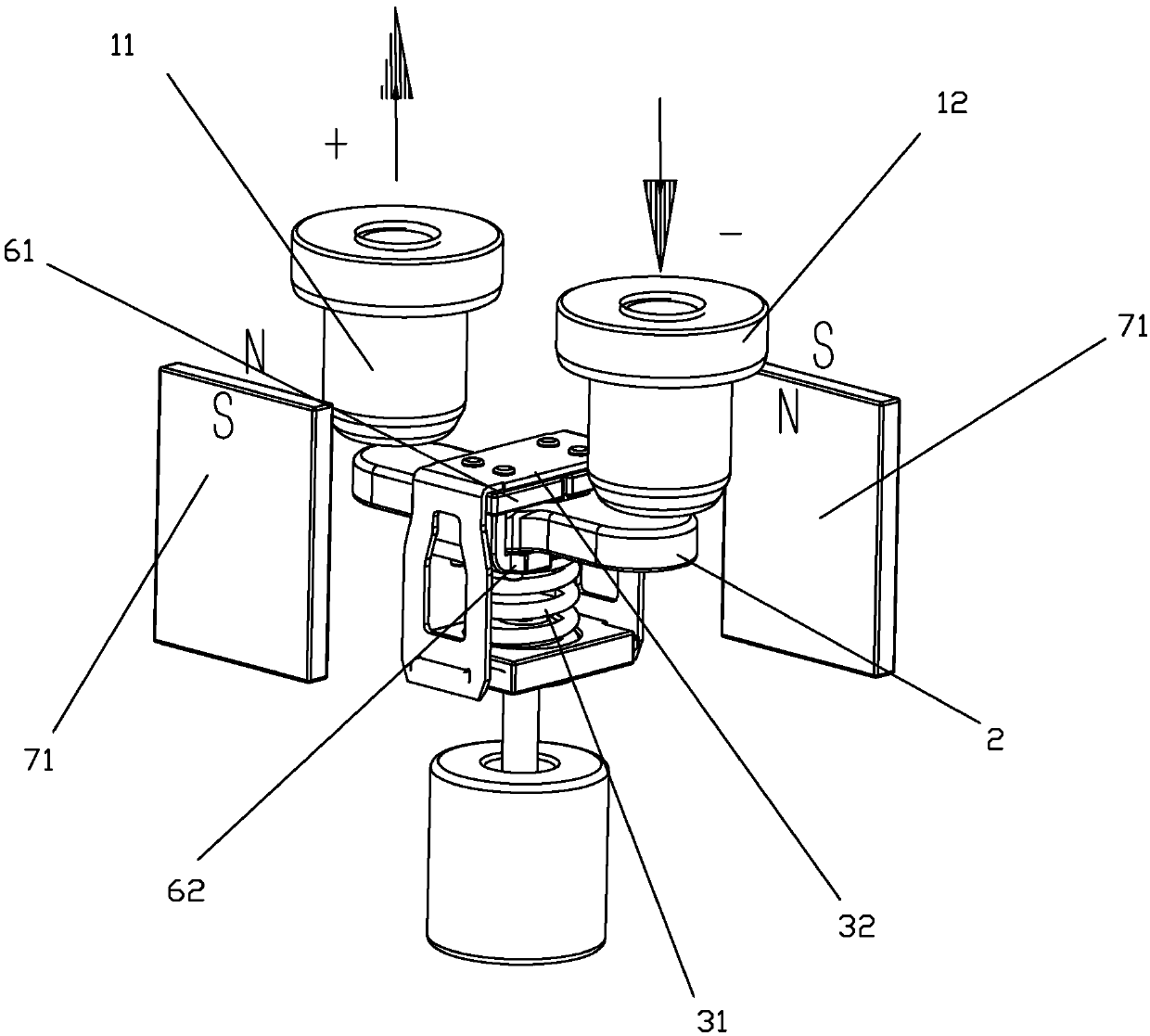
[0043] see Figure 1 to Figure 14 As shown, a DC relay capable of extinguishing arcs and resisting short-circuit current of the present invention includes two static contact terminals 11, 12 for current inflow and current outflow respectively, and a straight-type movable reed 2 1. One is used to drive the moving reed 2 to move to realize the moving contact at both ends of the moving reed and the static contact at the bottom of the static contact lead-out end to contact or disconnect the push rod part 3 and two pieces of magnetic steel 71; two static The contact lead-out ends 11 and 12 are mounted on the casing 4 respectively, and a part of the moving reed 2 and the push rod part 3 are accommodated in the casing 4, and the push rod part 3 is also connected with the moving iron core 5 in the magnetic circuit structure , under the action of the magnetic circuit, the push rod part 3 drives the movable reed 2 to move upwards, so that the movable contacts at both ends of the movable...
Embodiment 2
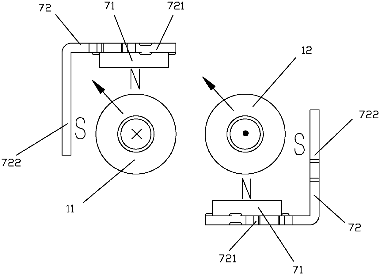
[0064] see Figure 15 As shown, a DC relay capable of extinguishing arcs and resisting short-circuit current of the present invention differs from Embodiment 1 in that the magnetic poles of the two magnetic steels 71 facing the moving and static contacts are set oppositely, specifically , among the two pieces of magnetic steel 71, the magnetic pole of a piece of magnetic steel 71 corresponding to the side of the static contact lead-out end 11 facing the corresponding moving and static contact is set as N pole, corresponding to the side of the static contact lead-out end 12 The magnetic pole of one side of a piece of magnetic steel 71 facing the corresponding moving and static contact is also set as S pole. In this embodiment, the magnetic field formed by the cooperation of the two magnetic steels 71 and the two yoke clips 72 can be formed as follows Figure 15 The magnetic blowing force in the direction indicated by the middle arrow, the magnetic blowing force in two directio...
Embodiment 3
[0067] see Figure 16 to Figure 17 As shown, a DC relay capable of extinguishing arcs and resisting short-circuit current in the present invention differs from Embodiment 1 in that the upper magnetic conductor 61 is an upper yoke, and the upper yoke is fixed on two On the shell of a static contact lead-out end, like this, when the moving contact of moving reed 2 and the static contact of static contact lead-out 11,12 are not in contact with (that is, when the contacts are disconnected), the upper lead There is a preset gap between the magnet 61 (upper yoke) and the lower magnetic conductor 62 (lower armature), and the movable contact of the movable reed 2 is in contact with the static contacts of the static contact terminals 11 and 12. When mating, the upper magnetizer 61 and the lower magnetizer 62 are in contact, that is, there is basically no gap between the upper magnetizer 61 and the lower magnetizer 62 .
[0068] Embodiment three
[0069] see Figure 18 to Figure 20 A...
PUM
 Abstract
Description
Claims
Application Information
 - R&D
- Intellectual Property
- Life Sciences
- Materials
- Tech Scout
- Unparalleled Data Quality
- Higher Quality Content
- 60% Fewer Hallucinations
Browse by: Latest US Patents, China's latest patents, Technical Efficacy Thesaurus, Application Domain, Technology Topic, Popular Technical Reports.
© 2025 PatSnap. All rights reserved.Legal|Privacy policy|Modern Slavery Act Transparency Statement|Sitemap|About US| Contact US: help@patsnap.com