
Annular truss type deployable antenna mechanism based on 3R-RRP mechanism unit

A mechanism unit and truss-type technology, which is applied in the field of antenna machinery, can solve the problems of single configuration, increased folding ratio, and high cost, and achieve the effects of low processing and manufacturing costs, simple structure, and large folding ratio

Pending Publication Date: 2019-04-19
YANSHAN UNIV
View PDF0 Cites 8 Cited by
  • Summary
  • Abstract
  • Description
  • Claims
  • Application Information

AI Technical Summary

Problems solved by technology

The deployment process of this scheme is simple, and the driving source is single. However, due to the presence of multiple sets of bevel gears meshing, the cost of processing and assembling the overall mechanism is relatively high. At the same time, the folding ratio of this scheme needs to be improved.
Relevant scientific research institutions in my country have carried out a lot of research work on the ring truss space deployable antenna mechanism and achieved remarkable results. However, there are still few ring truss deployable antennas in orbit and their configurations are relatively simple. Therefore, , it is necessary to propose some circular truss-type deployable antenna mechanisms with simple structure, large folding ratio and high rigidity to meet the needs of different space missions

Method used


Image

  • Annular truss type deployable antenna mechanism based on 3R-RRP mechanism unit
  • Annular truss type deployable antenna mechanism based on 3R-RRP mechanism unit
  • Annular truss type deployable antenna mechanism based on 3R-RRP mechanism unit

Examples


Embodiment 1

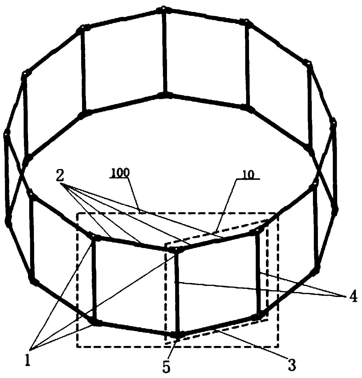
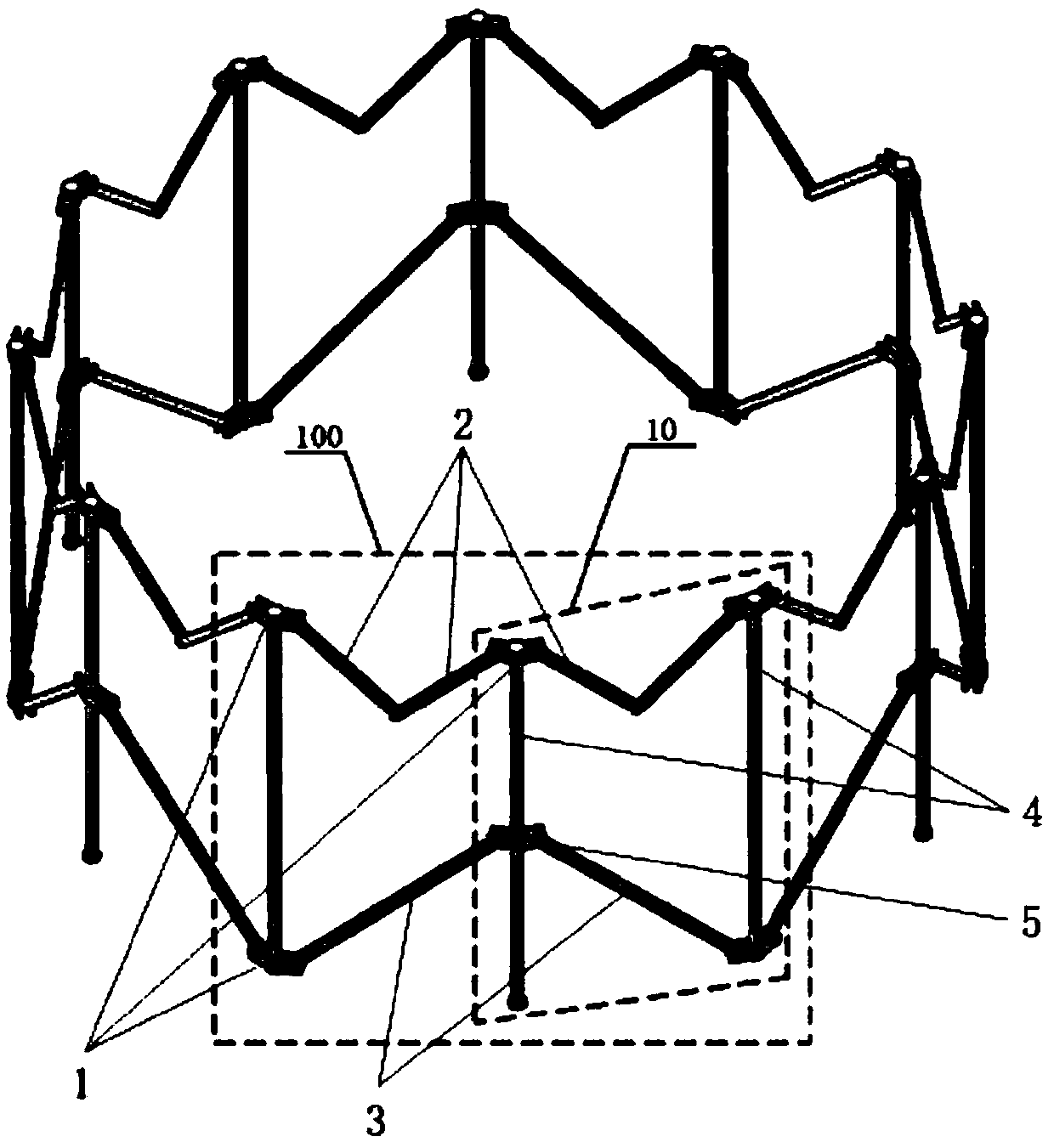
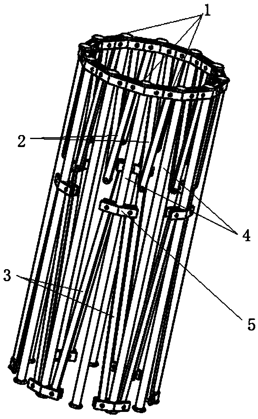
[0027] Embodiment 1, the operation process of the ring truss type deployable antenna mechanism based on the 3R-RRP mechanism unit of the present invention can be as follows, take 12 3R-RRP mechanism units 10, and 12 3R-RRP mechanism units 10 are in pairs , by sharing a support rod 4, a fixed node connecting piece 1 and a moving node connecting piece 5 to form six combined mechanism units 100; the structures of the six combined mechanism units 100 are exactly the same, and the adjacent combined mechanism units 100 The space is connected by sharing a support rod 4 and two fixed node connectors 1 to form a multi-faceted ring truss mechanism.

[0028]The 3R-RRP mechanism unit 10 mainly includes two support rods 4 , one long connecting rod 3 , two short connecting rods 2 , three fixed node connectors 1 and one moving node connector 5 . The two support rods 4 are identical in structure, and are symmetrically arranged on both sides of the 3R-RRP mechanism unit 10; An open slot 11, t...


PUM


Abstract

The invention discloses an annular truss type deployable antenna mechanism based on 3R-RRP mechanism units. The annular truss type deployable antenna mechanism comprises 2N 3R-RRP mechanism units, wherein the 2N 3R-RRP mechanism units are arranged in pairs, and form N combined mechanism units through sharing a supporting rod, a fixed node connecting member and a motion node connecting member in each pair; the N combined mechanism units are of the identical structure, the adjacent combined mechanism units are connected with each other through sharing one supporting rod and two fixed node connecting members, and the combined mechanism units form a multi-surface annular truss mechanism together; each 3R-RRP mechanism unit mainly comprises two supporting rods, a long connecting rod, two shortconnecting rods, three fixed node connecting members and a motion node connecting member; and the length of each short connecting rod is half the length of each long connecting rod, and the length ofeach supporting rod is greater than three times of the length of each short connecting rod. The annular truss type deployable antenna mechanism has the advantages of simple overall mechanism structure, flexible movement and low processing and manufacturing costs, and can be used as a supporting mechanism in the field of large-diameter satellite-borne antennas.

Description

technical field [0001] The invention belongs to the field of antenna machinery, and in particular relates to a ring truss type expandable antenna mechanism based on a 3R-RRP mechanism unit. Background technique [0002] With the rapid development of satellite communications, earth observation, and other space science enterprises, the needs of space agencies are becoming more and more urgent. Due to the limitation of the space of the launch vehicle, the space mechanism is required to be folded during the launch phase, and it is required to be unfolded to the working state after entering the orbit, and to maintain a certain degree of rigidity and precision. Therefore, most aerospace space mechanisms are deployable mechanisms. At present, space deployable mechanisms have been widely used in the fields of solar wing deployment mechanisms, space docking mechanisms, space station skeletons, lunar rover suspensions, and large-diameter space deployable antennas. The 60-meter deploy...

Claims


Application Information

Patent Timeline
IPC IPC(8): H01Q1/08
CPCH01Q1/08H01Q1/084
Inventor 赵永生韩博许允斗姚建涛郑东郭路瑶郭笑宇
Owner YANSHAN UNIV
Features
  • Generate Ideas
  • Intellectual Property
  • Life Sciences
  • Materials
  • Tech Scout
  • Unparalleled Data Quality
  • Higher Quality Content
  • 60% Fewer Hallucinations
Learn More