
Special heat radiation apparatus for local heating points of electrical equipment

A technology for electrical equipment and heat dissipation devices, which is applied in the field of special heat dissipation devices for local heating points of electrical equipment, can solve problems such as equipment damage, personal injury, and irregular installation, so as to slow down the aging speed of insulation, and facilitate processing and installation. Ensure the effect of safe and stable operation

Inactive Publication Date: 2019-04-19
ANHUI JINMEI ZHONGNENG CHEM IND
View PDF9 Cites 0 Cited by
  • Summary
  • Abstract
  • Description
  • Claims
  • Application Information

AI Technical Summary

Problems solved by technology

[0002] In the operation of large-scale factory power supply and distribution systems, due to irregular installation, overload operation, poor contact, surface oxidation, poor ventilation, etc., the contact parts of the electrical equipment often experience severe local heating of the electrical equipment, with local points as high as Above 120°C, especially for high-current equipment in high-temperature seasons, if forced heat dissipation is not adopted, the insulation material near the heating point will accelerate aging, which will cause system shutdown if it is mild, and equipment and personal injury accidents if severe
[0003] At present, the commonly used forced heat dissipation measure is to place a fan at the hot spot as a heat dissipation device, but the air volume of the existing industrial fans on the market cannot be gathered, and the heat dissipation effect is not up to the requirement, and most of the materials used are carbon steel. Contact with electrical equipment during movement and movement increases the risk of equipment damage and personal injury

Method used


Image

  • Special heat radiation apparatus for local heating points of electrical equipment

Examples


Embodiment Construction

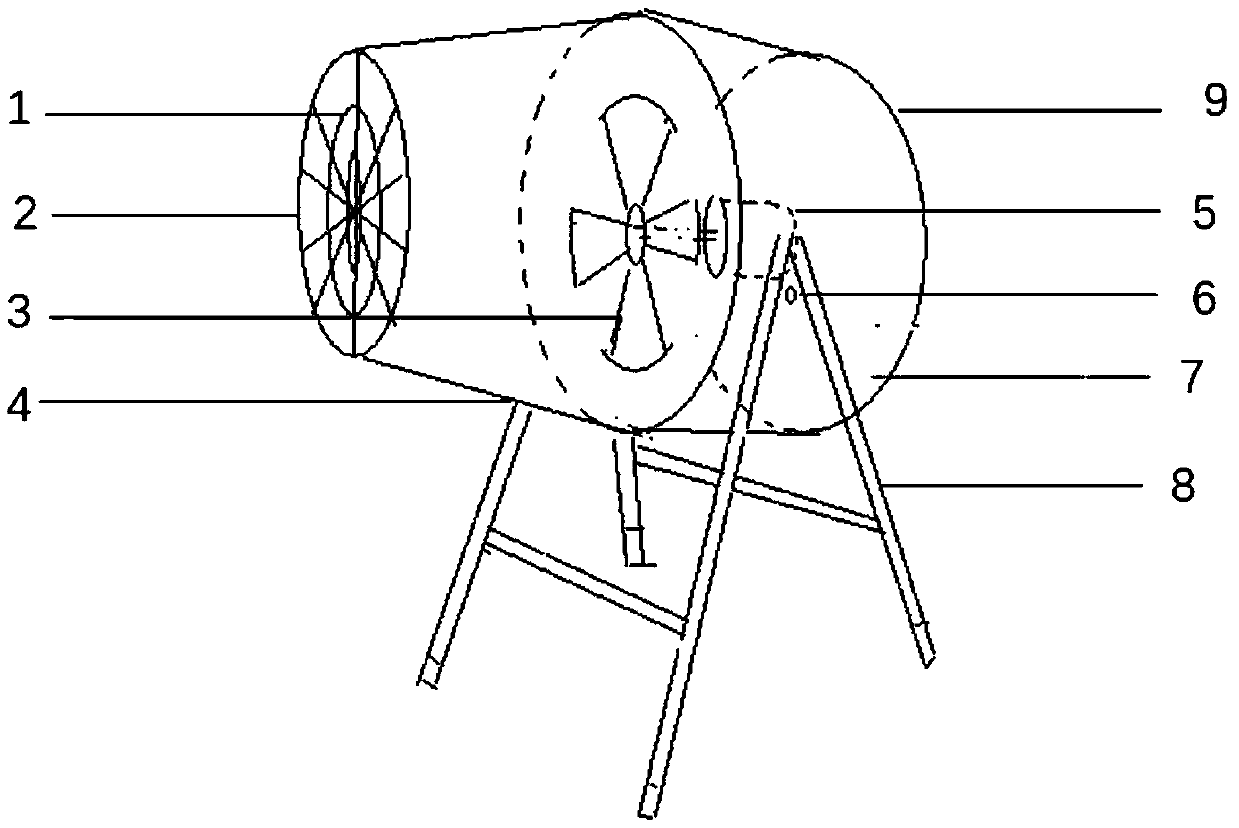
[0023] The following describes several preferred embodiments of the present invention with reference to the accompanying drawings, so as to make the technical content clearer and easier to understand. The present invention can be embodied in many different forms of embodiments, and the protection scope of the present invention is not limited to the embodiments mentioned herein.

[0024] In the drawings, components with the same structure are denoted by the same numerals, and components with similar structures or functions are denoted by similar numerals. The size and thickness of each component shown in the drawings are shown arbitrarily, and the present invention does not limit the size and thickness of each component. In order to make the illustration clearer, the thickness of parts is appropriately exaggerated in some places in the drawings.

[0025] Such as figure 1 As shown, a preferred embodiment of the present invention is a special cooling device for local heating po...


PUM

PropertyMeasurementUnit
Poweraaaaaaaaaa
Tensile strengthaaaaaaaaaa

Abstract

The invention discloses a special heat radiation apparatus for local heating points of electrical equipment, and relates to the technical field of operation and maintenance of factory power supply anddistribution system. The special heat radiation apparatus includes a motor, fan blades, an air inlet, a cylindrical glass fibre air hose, a tapered glass fibre air collection tube, an air port adjusting bolt, an insulated fixing support and a guard net, wherein the fan blades are fixedly arranged on an output shaft of the motor; the motor is fixed at the middle of the cylindrical glass fibre airhose; the cylindrical glass fibre air hose is movably arranged on the insulated fixing support; and the guard net is arranged at the air outlet. The special heat radiation apparatus for local heatingpoints of electrical equipment adopts well-insulated materials to replace conductive carbon steel materials used in a traditional fan, has good insulation during movement and use so as to ensure equipment and personal safety, and has a simple wind collecting structure, thus effectively improving the heat dissipation performance of the fan, eliminating the hidden danger of electrical equipment heating, and slowing down the insulation aging speed of equipment.

Description

technical field [0001] The invention relates to the technical field of operation and maintenance of power supply and distribution systems in factories, in particular to a heat dissipation device for local heating points of electrical equipment. Background technique [0002] In the operation of large-scale factory power supply and distribution systems, due to irregular installation, overload operation, poor contact, surface oxidation, poor ventilation, etc., the contact parts of the electrical equipment often experience severe local heating of the electrical equipment, with local points as high as Above 120°C, especially for high-current equipment in high-temperature seasons, if forced cooling is not adopted, the insulating materials near the heating point will accelerate aging, which will cause system shutdown if it is mild, and equipment and personal injury accidents if severe. [0003] At present, the commonly used forced heat dissipation measure is to place a fan at the h...

Claims


Application Information

Patent Timeline
IPC IPC(8): H05K7/20
CPCH05K7/20909
Inventor 邓永新侯子岭彭永刘明星刘坤邓人杰
Owner ANHUI JINMEI ZHONGNENG CHEM IND
Learn More