Electrical equipment joint temperature early warning monitoring system

A technology for electrical equipment and early warning systems, applied in non-electrical signal transmission systems, thermometers, signal transmission systems, etc., can solve problems such as temperature sensor scrapping, failure to reach early warning, and short abnormal processing time, so as to eliminate the cause of false alarms, The effect of avoiding false alarms

Inactive Publication Date: 2020-06-23
北京智盟信通科技有限公司
View PDF8 Cites 11 Cited by
  • Summary
  • Abstract
  • Description
  • Claims
  • Application Information

AI Technical Summary

Problems solved by technology

[0004] These solutions only solve the problem of temperature acquisition and temperature acquisition signal transmission, and have the following disadvantages: 1) At present, all equipment joint temperature online monitoring systems adopt a fixed threshold alarm mode, and if the threshold value is set too low, it will easily cause false alarms (equipment The heating of the joint is related to the load current and the ambient temperature). When the threshold is set too high, the problem of false alarms is solved, but the alarm temperature is too high, which may easily cause equipment overheating failures. At the same time, when overheating is found, the abnormal processing time for the operator is short. Easy to expand the scope of the accident
[0005] 2) Most of the temperature measuring sensors are composed of electronic components. When the alarm temperature is high, the limit temperature of these electronic components has been reached. After an alarm, the temperature sensor may be scrapped.
[0006] 3) Since there is no monitoring of load current and ambient temperature in the system, it is impossible to accurately predict the trend of temperature development and fail to achieve the purpose of early warning

Method used


Image

  • Electrical equipment joint temperature early warning monitoring system
  • Electrical equipment joint temperature early warning monitoring system

Examples


Embodiment Construction

[0027] The technical solutions in the embodiments of the present invention will be clearly and completely described below in conjunction with the accompanying drawings in the embodiments of the present invention. Obviously, the described embodiments are only some of the embodiments of the present invention, not all of them. Based on The embodiments of the present invention and all other embodiments obtained by persons of ordinary skill in the art without making creative efforts belong to the protection scope of the present invention.

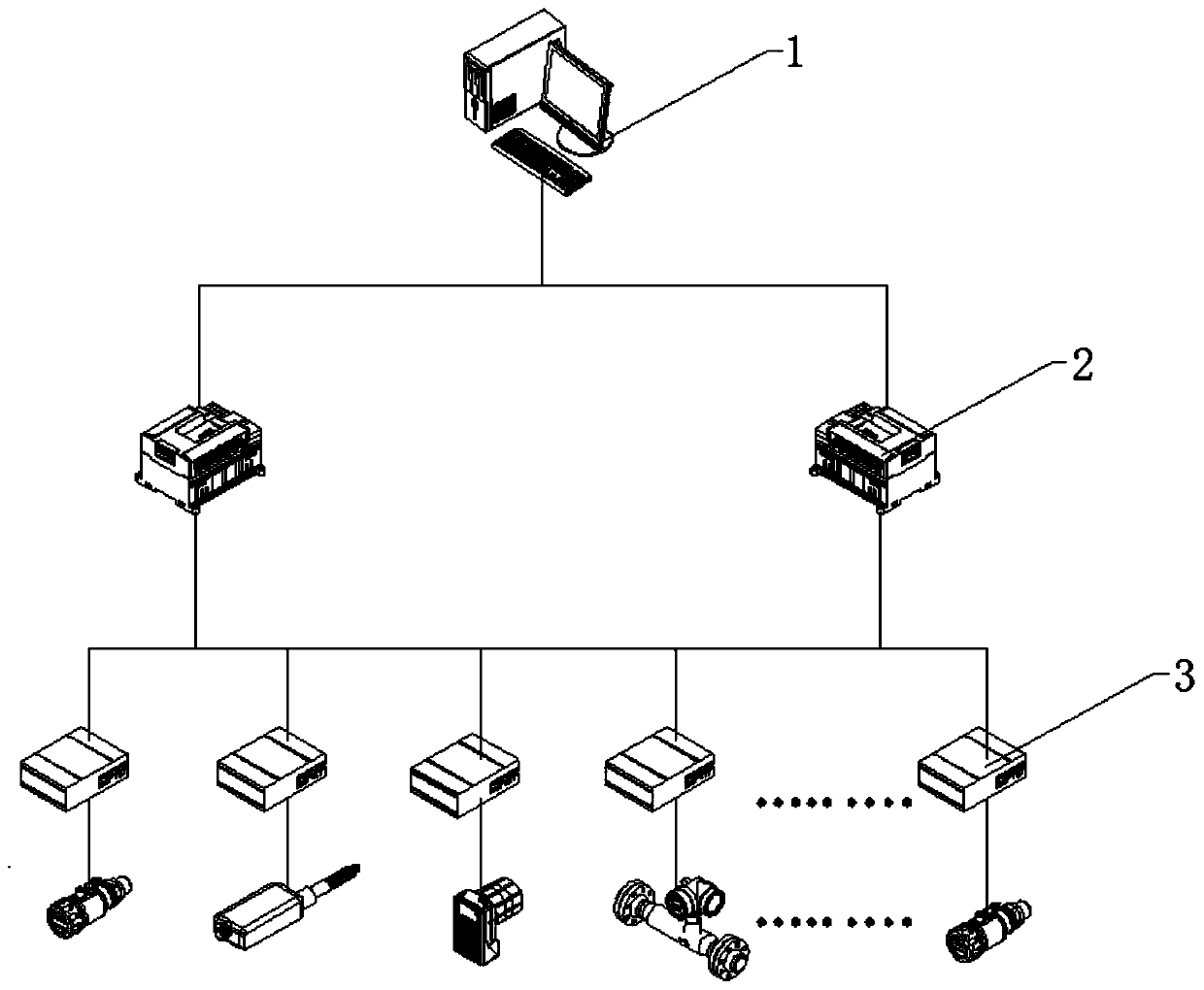
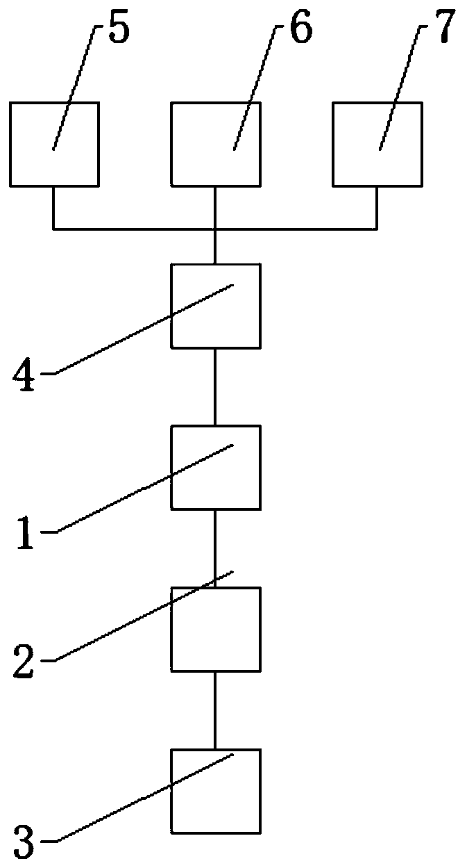
[0028] see Figure 1-2 , the present invention provides a technical solution:

[0029] An electrical equipment joint temperature early warning monitoring system, comprising an equipment joint temperature early warning system host 1, a wireless temperature measurement receiver 2 and a wireless temperature measurement module 3, the equipment joint temperature early warning system host 1 is equipped with electrical equipment joint temperature early...


PUM


Abstract

The invention relates to the technical field of electrical equipment detection and especially relates to an electrical equipment joint temperature early-warning monitoring system. The system comprisesan equipment joint temperature early warning system host, a wireless temperature measurement receiver and a wireless temperature measurement module. Electrical equipment joint temperature early warning system software is installed in the equipment joint temperature early warning system host. In the invention, a load current and an environment temperature of electrical equipment is introduced intothe electrical equipment joint temperature monitoring and early warning system so that sudden change temperature early warning, three-phase inconsistent temperature early warning and trend analysis temperature early warning become possible. A temperature early warning threshold value is greatly reduced, false alarm possibility of temperature early warning is eliminated, abnormity can be found inan early stage of temperature abnormity, precious time is gained for abnormity processing, insulation accidents and fire accidents caused by a continuous temperature rise are avoided, and safe and stable operation of electrical equipment is guaranteed.

Description

technical field [0001] The invention relates to the technical field of electrical equipment detection, in particular to an electrical equipment joint temperature early warning monitoring system. Background technique [0002] The online monitoring technology of temperature measurement for electrical equipment joints has been developed in the power system for almost 20 years, and various technologies have been implemented, from the initial optical fiber temperature measurement to the later wireless temperature measurement, and finally to the current surface acoustic wave temperature measurement. For example: On-line monitoring system for switch cabinet joint temperature: use optical fiber temperature sensor to collect the temperature of switch cabinet joint, the collected temperature data will be transmitted to the temperature alarm online monitoring system through optical fiber transmission, and the online monitoring system will compare the collected temperature signal with th...

Claims


Application Information

Patent Timeline
Patent Type & Authority Applications(China)
IPC IPC(8): G01K13/00G01K1/02G08C17/02G08C23/06G01K1/024
CPCG01K13/00G01K1/024G08C17/02G08C23/06
Inventor 李自力许雷贾月茂马睿浩王海龙谢茜崔玮张明星
Owner 北京智盟信通科技有限公司
Why Eureka
Try Eureka