
Method for removing a filler from a cavity present in a component and device for carrying out the method

A technology of components and cavities, applied in the field of equipment used to remove fillers from cavities existing in components and for performing this, can solve the problems of time-consuming powder, cannot be completely removed from cavities, etc., and achieve optimal movement The effect of the process

Active Publication Date: 2021-06-25
SIEMENS AG
View PDF9 Cites 0 Cited by
  • Summary
  • Abstract
  • Description
  • Claims
  • Application Information

AI Technical Summary

Problems solved by technology

The problem according to this document is that the components produced in the powder bed by means of additive manufacturing methods, such as laser melting, must then be removed from the component without melting the particles of the powder bed
In the case of complex cavity geometries or in the case of large cavities, this method is time-consuming and there is a risk that the powder will not be completely removed from the cavity

Method used


Image

  • Method for removing a filler from a cavity present in a component and device for carrying out the method
  • Method for removing a filler from a cavity present in a component and device for carrying out the method
  • Method for removing a filler from a cavity present in a component and device for carrying out the method

Examples


Embodiment Construction

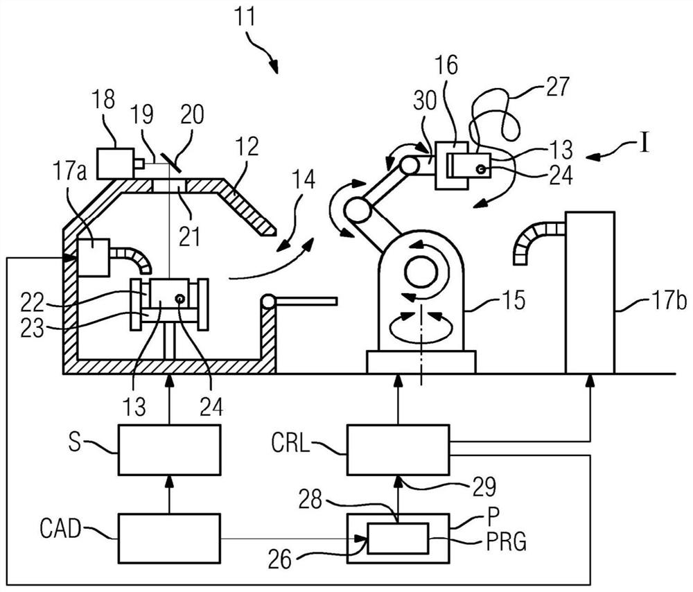
[0030] The manufacturing unit 11 has a device 12 for the additive manufacturing of components 13 , wherein this is a device for selective laser melting. The device has a material interface 14 in the form of a flap, through which components can be accommodated in a holder 16 by a robot 15 with four axes indicated by double-headed arrows. Furthermore, the production unit 11 has a plurality of suction devices 17a, 17b.

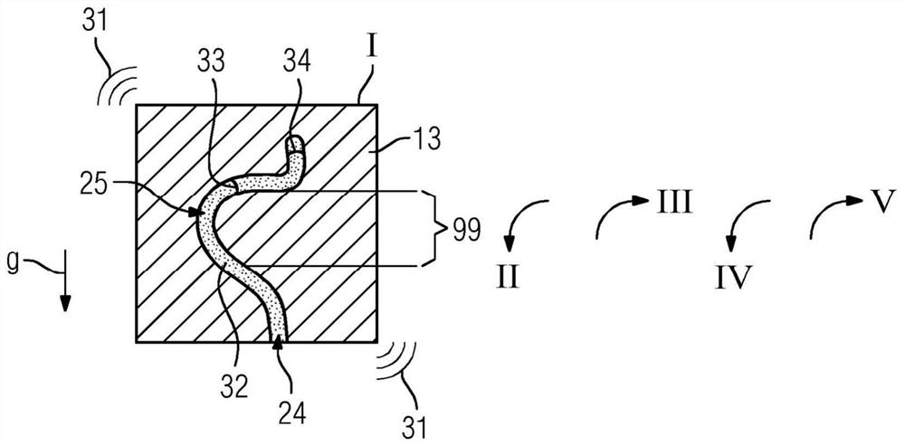
[0031] The structure of the apparatus 12 for selective laser melting is known and described in figure 1 are shown schematically only. The laser 18 generates a laser beam 19 which is directed by the steering optics 20 via the window 21 onto the powder bed 22 so that the component 13 is layered on the build platform 23 . After the production of the component 13 has been completed, the component 13 can first be exposed from the powder bed by means of the suction device 17a. In addition, some powder may have passed through the communication port 24 from the cavity...


PUM


Abstract

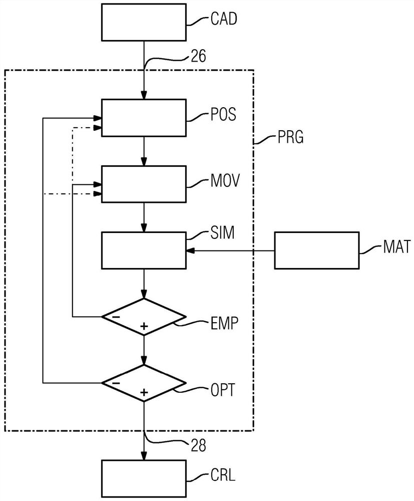
The invention relates to a method for removing a filling material from a cavity present in a component (13) via a connecting opening (24). For this purpose, components produced in the plant ( 12 ), for example by means of selective laser melting, can be removed by a robot ( 15 ) and emptied starting from a starting position I via a programmed motion profile ( 27 ). According to the invention, the required movements ( 27 ) are simulated by means of a computer program (RPG) in order to ensure that the support material is removed as completely as possible in a short time. The simulation results are delivered to the control device (CRL) of the robot (15). The invention also relates to a manufacturing plant (11) in which said removal method is integrated, and to a computer program (RPG) adapted to said calculation.

Description

technical field [0001] The invention relates to a method for removing filler material from a cavity present in a component, wherein the cavity has a communication opening to the surroundings of the component. In this case, the following method steps are performed: the component is held in a movable holder and the component is moved while simultaneously removing the filling material through the connection opening. The invention also relates to a device which is suitable for carrying out the method described at the outset. Background technique [0002] The method described at the outset is described, for example, in patent document US 2016 / 0074940 A1. The problem according to this document is that the components produced in the powder bed by means of additive manufacturing methods, such as laser melting, must then be removed from the component by non-fused particles of the powder bed. It is particularly problematic to remove unfused particles of the powder bed in cavities pr...

Claims


Application Information

Patent Timeline
IPC IPC(8): B22F3/105B28B1/00B29C64/153
CPCB33Y40/00B29C64/153B29C64/35B22F2999/00B08B5/04B08B7/02B08B7/026B08B9/00B22D29/005B22F10/73B22F10/28B22F12/88B22F10/68B22F10/80B33Y40/20Y02P10/25B22F2202/01
Inventor C.基纳
Owner SIEMENS AG
Learn More