Roller-cone polycrystalline diamond compact (PDC) two-stage cutting compound drill bit

A compound drill bit and roller cone technology, which is applied in the direction of drill bits, drilling equipment, earthwork drilling and production, etc., can solve the problem of slowing down of mechanical drilling speed of PDC drill bits and roller cone bits, increasing the investment and cost of surface pump equipment, cutting debris return, etc. Insufficient drainage space and other problems, to achieve the effect of realizing drilling efficiency, improving well deviation control ability, and improving drilling efficiency

Inactive Publication Date: 2019-04-23
LANZHOU CITY UNIV
View PDF5 Cites 6 Cited by
  • Summary
  • Abstract
  • Description
  • Claims
  • Application Information

AI Technical Summary

Problems solved by technology

[0009] The purpose of the present invention is to provide a PDC two-stage cutting composite drill bit, to solve the problems of increasing well depth, increasing rock hardness and plasticity, poor rock drillability, and increased drilling difficulty in the above-mentioned background technology. , the mechanical drilling speed of the PDC bit and the roller cone bit is slowed down, and the service life is shortened, which cannot meet the requirements of drilling speed increase; the local water head loss at the bottom of the cut hole is large, and the circulation pressure loss is large, which increases the equipment investment and cost of the surface pump group. ;The traditional composite drill bit has no cutting level distinction, and the cuttings flowback space is not large enough; PDC breaks rocks under in-situ stress and has serious wear and tear problems and deficiencies

Method used


Image

  • Roller-cone polycrystalline diamond compact (PDC) two-stage cutting compound drill bit
  • Roller-cone polycrystalline diamond compact (PDC) two-stage cutting compound drill bit
  • Roller-cone polycrystalline diamond compact (PDC) two-stage cutting compound drill bit

Examples


Embodiment approach

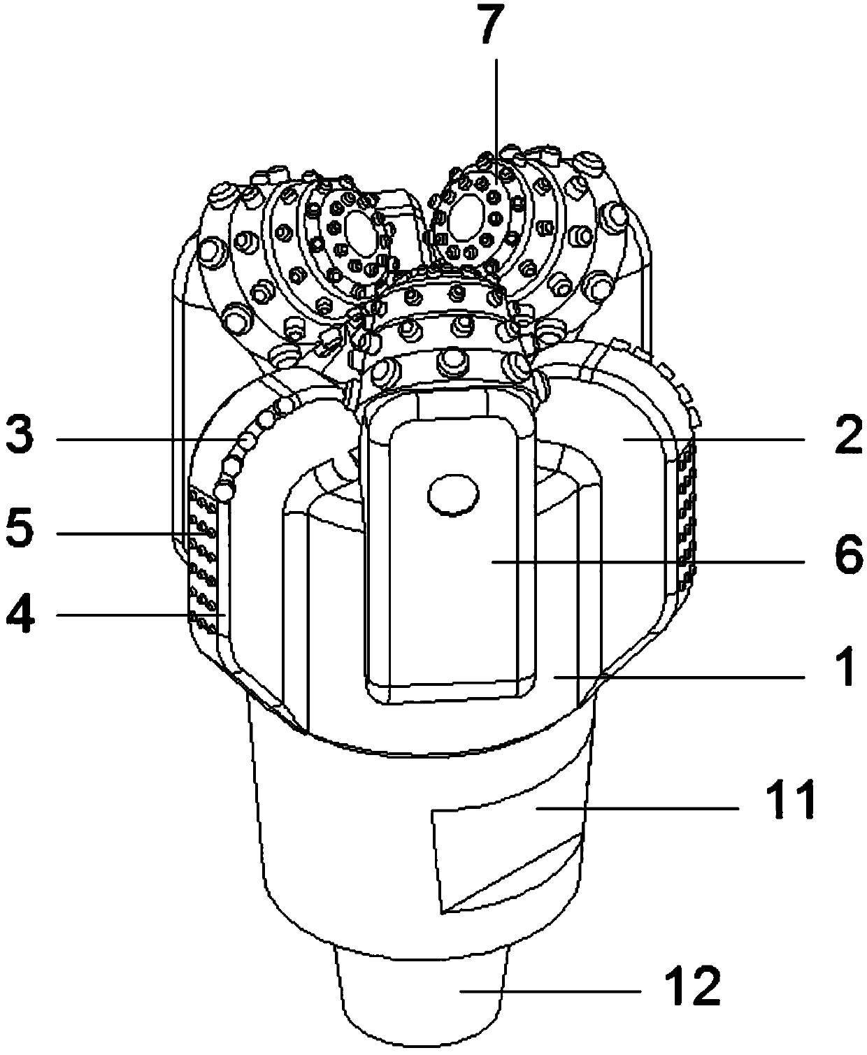
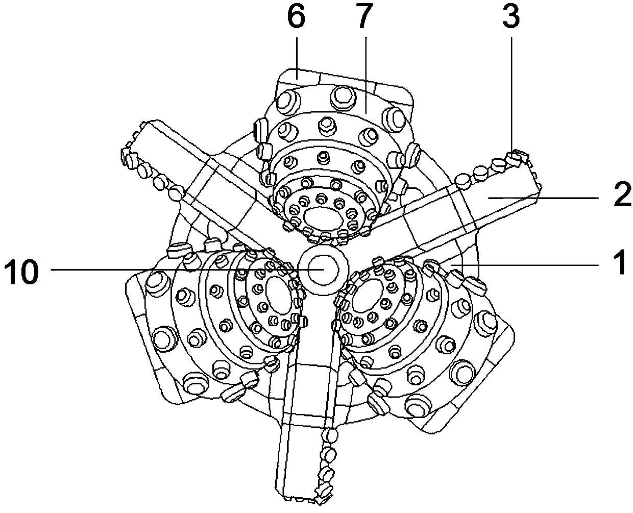
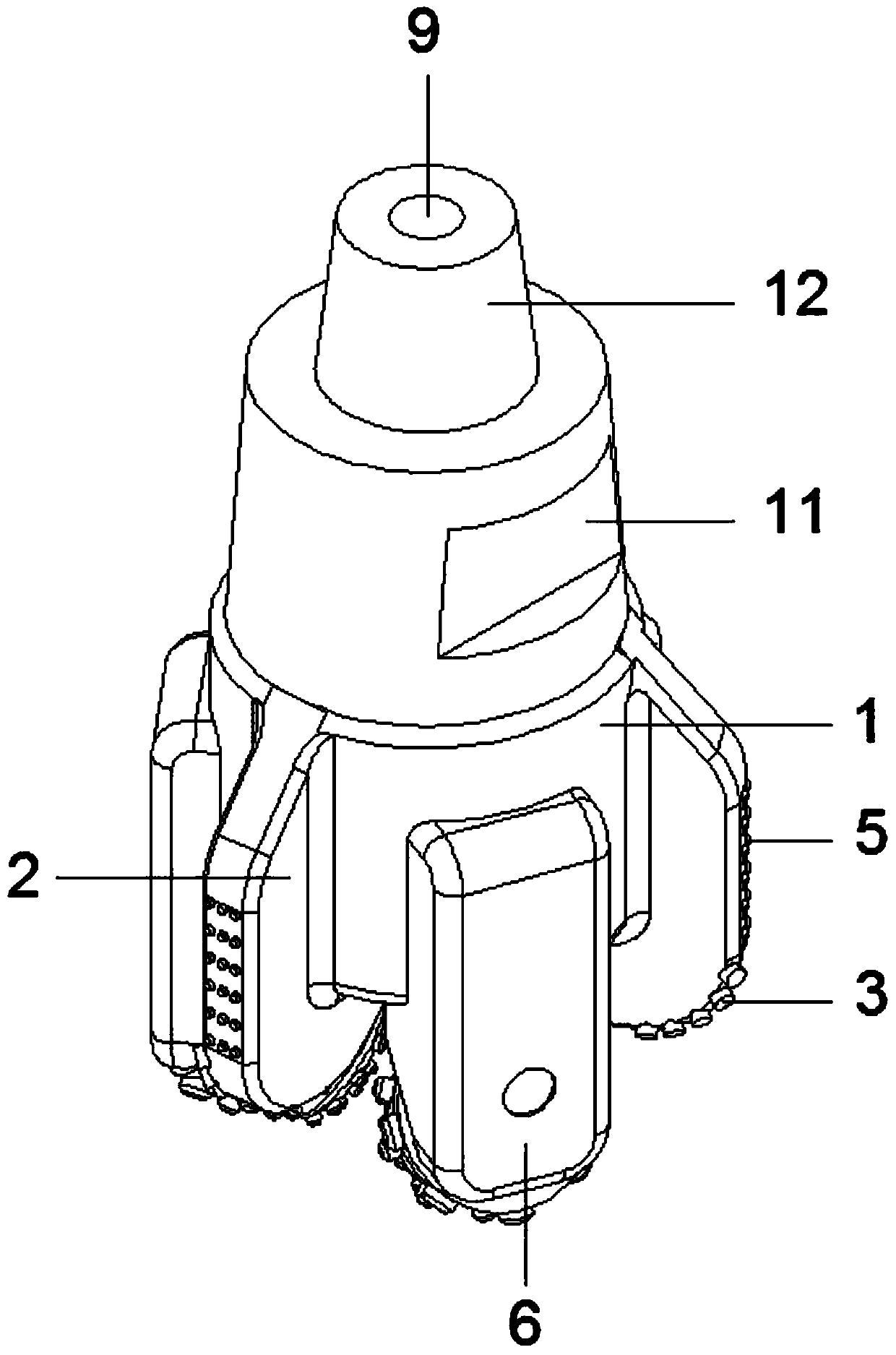
[0035] A roller cone PDC two-stage cutting compound drill bit, comprising: PDC bit body 1, blade 2, cutting teeth 3, gauge part 4, gauge teeth 5, oil storage chamber 6, cone 7, teeth 8, flow channel 9. Water eye 10, shackle groove 11, screw thread 12; the blade 2 is set on the top of the PDC bit body 1, and the blade 2 and the PDC bit body 1 are of an integrated structure; the cutting teeth 3 are welded and installed on the blade 2 one side of the top; the gauge part 4 is arranged on the outside of the blade 2, and the gauge part 4 is connected with the blade 2 by welding; the gauge teeth 5 are welded and installed on the outer wall of the gauge part 4; The oil cavity 6 is arranged on the top of the PDC bit body 1, and the oil storage cavity 6 is connected with the PDC bit body 1 by welding; the cone 7 is installed on the top of the oil storage cavity 6; the outer wall of the tooth 8 is welded and mounted on the cone 7 Above; the flow channel 9 is set through the middle positi...


PUM


Abstract

The invention provides a roller-cone polycrystalline diamond compact (PDC) two-stage cutting compound drill bit, comprising a PDC drill bit body, blade wings and roller cones, wherein the blade wingsare arranged at the top end of the PDC drill bit body, and the blade wings and the PDC drill bit body form an integral structure; cutting teeth are embedded and welded at one sides of the top ends ofthe blade wings; gauge protection parts are arranged at the outer sides of the blade wings, and are connected with the blade wings in a welding way; gauge protection teeth are embedded and welded on the outer walls of the gauge protection parts; an oil storage cavity is arranged at the top end of the PDC drill bit body. By improving a compound drill bit, the roller-cone PDC two-stage cutting compound drill bit has the advantages that the structural design is reasonable, layer-by-layer cutting can be realized, a roller-cone drill bit and a PDC drill bit complement the advantages of each other,and the drill bit is good in guiding effect, high in stability, strong in well deviation control ability, less in local hydraulic loss, low in energy consumption of ground power equipment, high in drilling efficiency, low in drilling cost and high in practicality; therefore, the problems and deficiencies raised in the background technology of the invention are effectively solved.

Description

technical field [0001] The invention relates to the technical field of oil and gas field development, and more specifically relates to a composite drill bit equipped with two layers for cutting rock. Background technique [0002] With the continuous development of oil and gas fields, my country's shallow oil and gas resources are decreasing year by year, and are developing towards deep and ultra-deep well oil and gas reservoirs. In recent years, my country's drill bit design theory and technology have developed rapidly, but to a certain extent, there is still a certain gap between them and foreign countries. Mainly manifested in drilling material technology, design process and manufacturing means. However, our country lacks more practical design and production core technologies. Many drill bit manufacturers have only made breakthroughs in one aspect, and a complete set of technologies is still in the simple imitation manufacturing stage, which greatly restricts the developmen...

Claims


Application Information

Patent Timeline
Patent Type & Authority Applications(China)
IPC IPC(8): E21B10/00E21B10/46E21B10/08
CPCE21B10/00E21B10/08E21B10/46
Inventor 孙艳超王国伟朱月珍
Owner LANZHOU CITY UNIV
Why Eureka
Try Eureka