Vehicle engine cooling fan and control method

A vehicle engine and cooling fan technology, applied in the direction of engine components, machines/engines, engine cooling, etc., can solve the problem of a single power source that cannot actively adjust the speed, reduce wear and tear, reduce the difficulty of vehicle adaptation, and improve The effect of generality

Inactive Publication Date: 2019-04-23
CHINA FIRST AUTOMOBILE
View PDF9 Cites 7 Cited by
  • Summary
  • Abstract
  • Description
  • Claims
  • Application Information

AI Technical Summary

Problems solved by technology

[0006] In order to solve the above problems, the present invention provides a vehicle engine cooling fan and a control method to solve the problems that the traditional vehicle cooling fan cannot actively adjust the speed and has a single power source during the working process.

Method used


Image

  • Vehicle engine cooling fan and control method
  • Vehicle engine cooling fan and control method
  • Vehicle engine cooling fan and control method

Examples


Embodiment 1

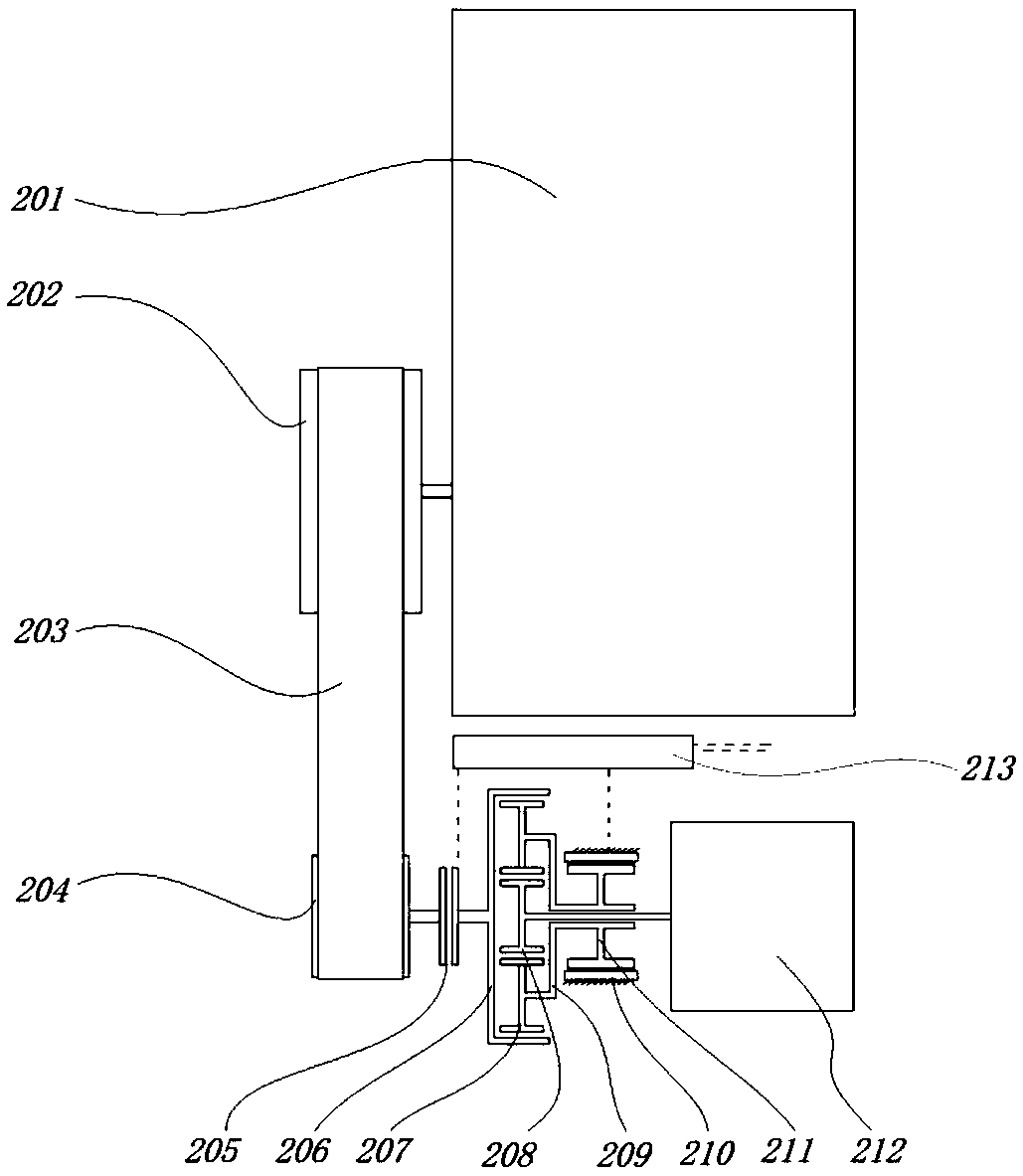
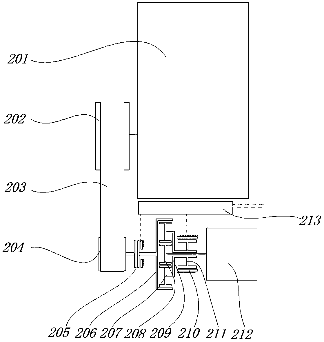
[0045] This embodiment provides a cooling fan for a vehicle engine, including: a cooling fan pulley, an electromagnetic clutch, a planetary gear row, a motor, a cooling fan and a control unit.

[0046] The engine pulley 202 of the engine 201 is connected to the cooling fan pulley 204 through the engine belt 203 , and the rotation speed of the engine 201 is directly proportional to the rotation speed of the cooling fan pulley 204 .

[0047] The electromagnetic clutch 205 is a single-combination position clutch (used for vehicles with relatively large starting resistance of the engine and small working torque of the cooling fan). The driving end of the electromagnetic clutch 205 is connected with the cooling fan pulley 204. The passive end of the clutch 205 is connected with the ring gear 206 of the planetary gear row. When the electromagnetic clutch 205 is combined, the rotation speed of the ring gear 206 of the planetary gear row is the same as the rotation speed of the cooling...

Embodiment 2

[0054] This embodiment provides a control method for a vehicle engine cooling fan, the vehicle engine cooling fan can be the vehicle engine cooling fan described in Embodiment 1, and:

[0055] When the electromagnetic clutch is a single combined position clutch:

[0056] The control methods include:

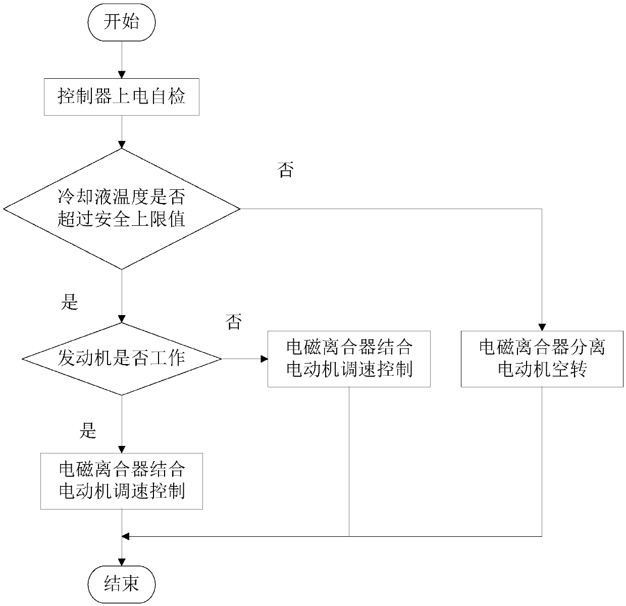
[0057] The control unit 213 starts a self-check after being powered on, and detects whether the temperature of the coolant from the engine exceeds a safety upper limit;

[0058] When it is detected that the engine coolant temperature is within a safe range, the control unit 213 controls the electromagnetic clutch 206 to disengage, and controls the rotor 211 of the electric motor to be in a free state. At this time, the cooling fan 212 has no power input, and the Cooling fan 212 stops working;

[0059] When it is detected that the engine coolant temperature exceeds the upper safety limit, it is judged whether the engine is in working condition:

[0060] When the engine 201 is i...


PUM


Abstract

The invention discloses a vehicle engine cooling fan and a control method. The vehicle engine cooling fan comprises a cooling fan belt wheel, an electromagnetic clutch, a planet gear row, an electricmotor and a cooling fan body; the engine is connected with the cooling fan belt wheel, the electromagnetic clutch is a single-engagement position type clutch, the active end of the electromagnetic clutch is connected with the cooling fan belt wheel, the passive end of the electromagnetic clutch is connected with a gear ring of the planet gear row, a planet wheel of the planet gear row is connectedwith a rotor of the electric motor through a planet carrier of the planet gear row, and a rotor of the electric motor is a hollow shaft, and is arranged on a rotating shaft between a sun wheel of theplanet gear row and the cooling fan body through a bearing in a sleeving manner. The problem that a traditional vehicle cooling fan cannot be subjected to active speed adjusting in the work process,and the power source is single is solved. The cooling fan can carry out cooling fan power source switching and speed adjusting in real time through the flexible control strategy.

Description

technical field [0001] The invention relates to the field of auto parts, in particular to a dual power source active speed regulation vehicle engine cooling fan based on a planetary gear row and a control method. Background technique [0002] The engine cooling fan sucks in air when the fan rotates, and makes it pass through the radiator to enhance the cooling capacity of the radiator, accelerate the cooling of the coolant, provide a reasonable temperature range for the engine working environment, and play an important role in the normal operation of the engine , is the core of the engine cooling system. [0003] At present, the common vehicle engine cooling fan is connected with the relevant belt of the engine through a pulley, and its power source is the engine, and the speed of the cooling fan is directly proportional to the engine speed. Due to the wide variation range of the engine speed during the running of the vehicle, it is difficult for the cooling fan to take int...

Claims


Application Information

Patent Timeline
Patent Type & Authority Applications(China)
IPC IPC(8): F01P5/04F01P7/04F04D27/00
CPCF01P5/04F01P7/048F01P2005/046F04D27/004
Inventor 李连强李胜韩宜伟
Owner CHINA FIRST AUTOMOBILE
Why Eureka
Try Eureka