Eureka AIR delivers breakthrough ideas for toughest innovation challenges, trusted by R&D personnel around the world.

Display panel and display device

A display panel and display area technology, applied in the direction of instruments, electrical digital data processing, electrical components, etc., can solve the problems of poor contact performance of metal materials, packaging failure, etc., to avoid direct contact, promote absorption capacity, and improve packaging effect Effect

Active Publication Date: 2019-04-23
XIAMEN TIANMA MICRO ELECTRONICS
View PDF5 Cites 11 Cited by
  • Summary
  • Abstract
  • Description
  • Claims
  • Application Information

AI Technical Summary

Problems solved by technology

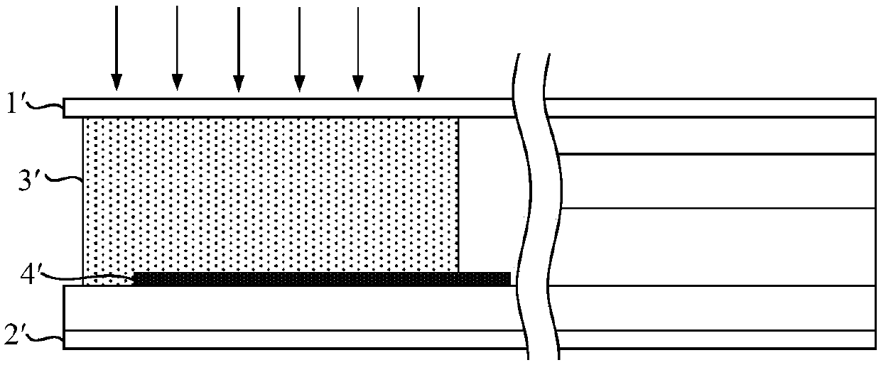
[0003] However, since the contact performance between the encapsulant 3' and the metal material is poor, if the encapsulant 3' is in direct contact with the underlayer metal 4', when the display panel is affected by external force factors, the encapsulant 3' will contact the underlayment. The metal 4' is detached, causing a gap between the two, which leads to package failure

Method used


Image

  • Display panel and display device
  • Display panel and display device
  • Display panel and display device

Examples


Embodiment Construction

[0035] In order to better understand the technical solutions of the present invention, the embodiments of the present invention will be described in detail below in conjunction with the accompanying drawings.

[0036] It should be clear that the described embodiments are only some of the embodiments of the present invention, not all of them. Based on the embodiments of the present invention, all other embodiments obtained by persons of ordinary skill in the art without making creative efforts belong to the protection scope of the present invention.

[0037] Terms used in the embodiments of the present invention are only for the purpose of describing specific embodiments, and are not intended to limit the present invention. As used in the embodiments of the present invention and the appended claims, the singular forms "a", "said" and "the" are also intended to include the plural forms unless the context clearly indicates otherwise.

[0038] It should be understood that the ter...


PUM


Abstract

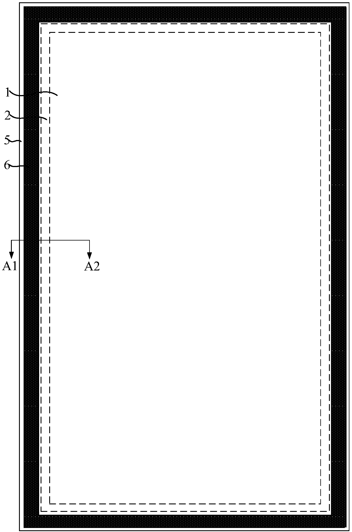
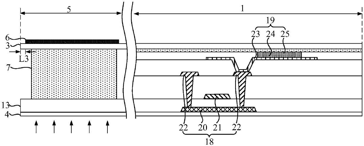
The embodiment of the invention provides a display panel and a display device and relates to the technical field of display, aiming at preventing a packaging adhesive from being in contact with firstcushion layer metal and improving the packaging effect of the display panel. The display panel comprises a display region, a non-display region, a first substrate and a second substrate, wherein the non-display region is arranged around the display region; the first substrate and the second substrate are arranged oppositely; the non-display region comprises a glass material packaging region; the glass material packaging region comprises the first cushion layer metal; the first cushion layer metal is located at one side, back on to the second substrate, of the first substrate.

Description

【Technical field】 [0001] The present invention relates to the field of display technology, in particular to a display panel and a display device. 【Background technique】 [0002] At present, encapsulation glue is usually used to encapsulate the display panel. like figure 1 as shown, figure 1 It is a schematic diagram of the packaging structure in the existing display panel. The display panel includes a first substrate 1' and a second substrate 2' that are oppositely arranged, and an encapsulation glue 3' and pads are provided between the first substrate 1' and the second substrate 2'. The layer metal 4' is used to reflect the laser light to the packaging glue 3' when laser sintering the packaging glue 3', so as to improve the melting effect of the packaging glue 3'. [0003] However, since the contact performance between the encapsulant 3' and the metal material is poor, if the encapsulant 3' is in direct contact with the underlayer metal 4', when the display panel is affe...

Claims


Application Information

Patent Timeline
Patent Type & Authority Applications(China)
IPC IPC(8): H01L51/52H01L27/32
CPCH10K59/40H10K59/12H10K59/8722G06F3/0446G06F2203/04103G06F3/04164G06F3/0412H10K50/8426
Inventor 彭超张中杰崔锐利刘忆
Owner XIAMEN TIANMA MICRO ELECTRONICS
Why Eureka
Eureka Blog
Learn More