Bidirectional transmission optical module capable of remotely adjusting wavelength

A two-way transmission and remote adjustment technology, applied in electromagnetic wave transmission system, optical fiber transmission, transmission system and other directions, can solve the problem that the optical communication module cannot adjust the communication wavelength remotely, and achieve the effect of convenient installation and deployment and improved flexibility.

Pending Publication Date: 2019-04-23
HANGZHOU XIN YUN TECH CO LTD
View PDF1 Cites 11 Cited by
  • Summary
  • Abstract
  • Description
  • Claims
  • Application Information

AI Technical Summary

Problems solved by technology

[0004] The technical problem to be solved by the present invention is: the technical problem that the optical communi

Method used


Image

  • Bidirectional transmission optical module capable of remotely adjusting wavelength
  • Bidirectional transmission optical module capable of remotely adjusting wavelength
  • Bidirectional transmission optical module capable of remotely adjusting wavelength

Examples


Example Embodiment

[0021] Example one:

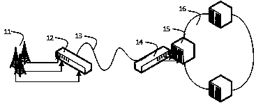
[0022] A bidirectional transmission optical module that can remotely adjust the wavelength, such as figure 1 As shown, it is a schematic diagram of the deployment scenario of the first embodiment. This embodiment is applied to the fronthaul of wireless communication. It is deployed between the active antenna unit 11 (AAU) and the distributed unit 15 (DU) and establishes a communication connection. The distributed unit 15 (DU) Usually connected to each other to form a DU ring 16. This embodiment includes several pairs of two-way optical communication units, a pair of combiners and demultiplexers, and an optical fiber 13. Each pair of two-way optical communication units are classified according to their deployment on the AAU end or the DU end. It is the terminal module 12 and the central office module 14. A pair of combiners and demultiplexers are respectively coupled to both ends of the optical fiber 13. The terminal module 12 is connected with the active ante...

Example Embodiment

[0026] Embodiment two:

[0027] A bidirectional transmission optical module capable of remotely adjusting the wavelength. In this embodiment, specific improvements are made to the transmitting module, the receiving module, and the multiplexer / demultiplexer. Such as Figure 4 As shown, it is a schematic diagram of the structure of the two-way optical communication unit of the second embodiment. In this embodiment, the transmitting module 41 includes a tunable laser 47, an isolator 45, a modulator 44, and a wave locker 46. The tunable laser 47 and the wave locker 46, The modulator 44 and the isolator 45 are connected. The receiving module 42 is a receiving module composed of PIN diodes. The combiner / demultiplexer 43 includes a circulator 48 and a tunable filter 49. The circulator 48 is coupled to the optical fiber 13, and the tunable filter 49 is coupled. On the circulator 48. The tunable filter 49 is an interleaver solution, and the circulator 48 can improve the filtering effect....

Example Embodiment

[0028] Embodiment three:

[0029] A bidirectional transmission optical module capable of remotely adjusting the wavelength. In this embodiment, specific improvements are made to the transmitting module, the receiving module, and the multiplexer / demultiplexer. Such as Figure 5 As shown, it is a schematic diagram of the structure of the three-way optical communication unit of the embodiment. In this embodiment, the transmitting module includes a tunable laser 54, an isolator 55, a modulator and a wave locker 57, a tunable laser 54 and a wave locker 57, and a modulator. And the isolator 55 is connected, the receiving module 52 is a receiving module composed of a PIN diode or an avalanche diode, and the multiplexer / demultiplexer 53 is an optical cross wavelength division multiplexer. Coupling the optical cross-wavelength division multiplexer directly with the optical fiber 13 can reduce the use of components, and can be used in areas with general communication quality requirements,...


PUM


Abstract

The invention relates to the technical field of optical communication equipment, in particular to a bidirectional transmission optical module capable of remotely adjusting the wavelength. The bidirectional transmission optical module comprises a plurality pairs of bidirectional optical communication units, a pair of wave combiners and separators and an optical fiber; each pair of bidirectional optical communication units are correspondingly partitioned to be a terminal module and a local side module according to the fact of being deployed at an AAU end or a DU end respectively, and the pair ofwave combiners and separators are coupled to the two ends of the optical fiber respectively, wherein the terminal module is connected with the active antenna unit (AAU) and the first wave combiner and separator, and the local side module is connected with the distributive unit (DU) and the second wave combiner and separator; and each bidirectional optical communication unit comprises a receivingmodule, a transmitting module and a wavelength control module, wherein the wavelength control module controls the transmitting module to transmit signal light with the corresponding wavelength according to an instruction received by the receiving module. The bidirectional transmission optical module has the substantial advantages that by means of the wavelength control modules, remote wavelength adjusting is achieved, and the system networking flexibility is improved; and by using single-fiber bidirectional transmission, the terminal modules and the local side modules have no physical difference, and installation and deployment are convenient.

Description

technical field [0001] The invention relates to the technical field of optical communication equipment, in particular to a bidirectional transmission optical module capable of remotely adjusting the wavelength. Background technique [0002] With the advent of 5G wireless communication, the wireless network architecture continues to evolve, services are re-sliced, and the forward and backhaul transmission from AAU to DU requires greater transmission bandwidth. At present, in the field of wireless fronthaul communication, common solutions are 100G CWDM4 direct transmission and 100G WDM PON solutions. The 100G CWDM4 direct transmission solution requires a large amount of optical fiber resources, and the 100GWDM PON solution requires a dedicated MAC layer and CPRI service conversion, and bidirectional transmission can The dimming module can save fiber resources and realize direct transparent transmission of CPRI services. Usually, a certain number of 5G network base stations an...

Claims


Application Information

Patent Timeline
IPC IPC(8): H04B10/2575H04B10/572
CPCH04B10/25753H04B10/572
Inventor 王宗旺夏晓亮
Owner HANGZHOU XIN YUN TECH CO LTD
Why Eureka
Try Eureka