Al technical title is built by PatSnap Al team. It summarizes the technical point description of the patent document.
A technology of punching device and stapler, which is applied in binding, metal processing, etc., can solve the problems of high cost of binding equipment, consumption of staff's physical strength, and complicated operation of binding equipment, so as to improve service life, improve work efficiency, Convenient fixed effect
Inactive Publication Date: 2019-04-26
临沂九一电子科技有限公司
View PDF9 Cites 3 Cited by
Summary
Abstract
Description
Claims
Application Information
AI Technical Summary
This helps you quickly interpret patents by identifying the three key elements:
Problems solved by technology
Method used
Benefits of technology
Problems solved by technology
[0002] Printing companies and book production workshops will use book binding equipment. However, the current binding equipment is complicated to operate and consumes a lot of physical strength of the staff. At the same time, because the thickness of the paper to be bound is too high, the staples cannot be penetrated, which not only causes damage to the paper, but also Causes excessive consumption of staples, resulting in high cost of binding equipment
Method used
Image
Click on the blue label to locate the original text in one second.
Reading with bidirectional positioning of images and text.
Examples
Embodiment Construction
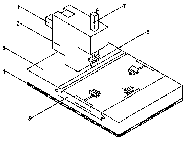
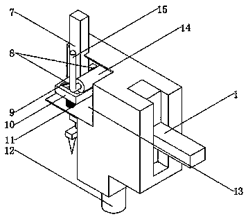
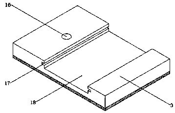
[0012] The present invention will be further elaborated below in conjunction with the accompanying drawings and specific embodiments.
[0013] A binding and punching device, including a stapler 1, a box body 2, a base 3, a rubber pad 4, a slide plate 5, a staple 6, a column 7, a linkage rod 8, a chute 9, an extruding plate 10, and a spring 11. Rotating column 12, transmission compartment 13, rotating shaft 14, control rod 15, rotating groove 16, sliding groove 17, sliding groove 18, fixed pin 19, staple groove 20, sliding convex contact 21, fixed clip convex contact 22. Fixing clip slideway 23, fixing pin groove 24 and fixing clip 25, a stapler 1 is arranged at one end of the top of the box body 2, a transmission cabin 13 is arranged inside the other end of the top of the box body 2, and the column 7 runs through the transmission cabin 13, and the column Staples 6 are installed at the bottom of 7, and extruding plate 10 is arranged at the bottom of column 7 in transmission com...
PUM
Abstract
The invention relates to a bookbinding punching device. The bookbinding punching device comprises a stapler, a box body, a base, a rubber cushion, a sliding plate, a staple, a vertical column, linkagerods, sliding grooves, an extrusion plate, a spring, a rotary column, a transmission cabin, a rotary shaft, a control rod, a rotary groove, a sliding plate groove, a sliding plate slot, fixing pins,a staple groove, a sliding plate convex contact, fixing clamp convex contacts, fixing clamp sliding ways, fixing pin grooves and fixing clamps. The stapler is arranged at one end of the top of the boxbody, the transmission cabin is arranged in the other end of the top of the box body, the vertical column penetrates through the transmission cabin, the staple is mounted at the bottom of the vertical column, the extrusion plate is arranged at the bottom, in the transmission cabin, of the vertical column and integrally connected with the vertical column, the spring is mounted at the bottom of theextrusion plate, and the sliding grooves are formed in the top, on the two sides of the vertical column, of the extrusion plate. The bookbinding punching device is convenient to operate, manpower andmaterial resources are saved, and the device is safe and reliable.
Description
technical field [0001] The invention relates to the field of municipal public facilities, in particular to a binding punching device. Background technique [0002] Printing companies and book production workshops will use book binding equipment. However, the current binding equipment is complicated to operate and consumes a lot of physical strength of the staff. At the same time, because the thickness of the paper to be bound is too high, the staples cannot be penetrated, which not only causes damage to the paper, but also Cause excessive consumption of staples, which in turn causes high cost of binding equipment. Contents of the invention [0003] The object of the present invention is to provide a kind of bookbinding punching device, to solve the above-mentioned technical problems, the present invention adopts the following technical solutions for realizing the above-mentioned purpose: [0004] A binding and punching device, including a stapler, a box body, a base, a ru...
Claims
Application Information
Patent Timeline
Application Date:The date an application was filed.
Publication Date:The date a patent or application was officially published.
First Publication Date:The earliest publication date of a patent with the same application number.
Issue Date:Publication date of the patent grant document.
PCT Entry Date:The Entry date of PCT National Phase.
Estimated Expiry Date:The statutory expiry date of a patent right according to the Patent Law, and it is the longest term of protection that the patent right can achieve without the termination of the patent right due to other reasons(Term extension factor has been taken into account ).
Invalid Date:Actual expiry date is based on effective date or publication date of legal transaction data of invalid patent.