
Multifunctional glass cutting device

A glass cutting, multi-functional technology, applied in glass cutting devices, glass manufacturing equipment, manufacturing tools, etc., can solve the problems of low work efficiency, non-professionals cannot cut materials, and the cutting process is complicated, and achieve the effect of improving cutting efficiency.

Pending Publication Date: 2019-04-26
SHAANXI UNIV OF SCI & TECH
View PDF0 Cites 1 Cited by
  • Summary
  • Abstract
  • Description
  • Claims
  • Application Information

AI Technical Summary

Problems solved by technology

[0002] Glass is something that can be seen everywhere in people's daily life. It has many shapes, and most of the cutting tools for glass are the same in the market. At the same time, it mainly depends on the craftsman's operation means and experience to cut different shapes, like a scale, Glass knives, etc. are all essential, and sometimes a cutting machine is used. The above-mentioned cutting process is complicated, resulting in low work efficiency and relatively large cutting errors.
[0003] At present, the known glass knives are all composed of a knife head and a knife body at the tip of a glass knife, but most non-professionals cannot cut materials in various shapes by themselves due to the technical and experience involved in operation, such as circular, Special shapes such as curved surfaces can only be completed by relevant experienced people
[0004] Traditional glass knives can only cut relatively simple shapes, and professional personnel are required to cut glass that is responsible for the shape. At the same time, traditional glass knives also cause certain losses to materials due to the uncertainty of measurement during the cutting process of materials. Moreover, when using traditional glass knives, the efficiency is not very high due to various reasons.

Method used


Image

  • Multifunctional glass cutting device
  • Multifunctional glass cutting device
  • Multifunctional glass cutting device

Examples


Embodiment Construction

[0031] The present invention will be further described in detail below in conjunction with the accompanying drawings, which are explanations rather than limitations of the present invention.

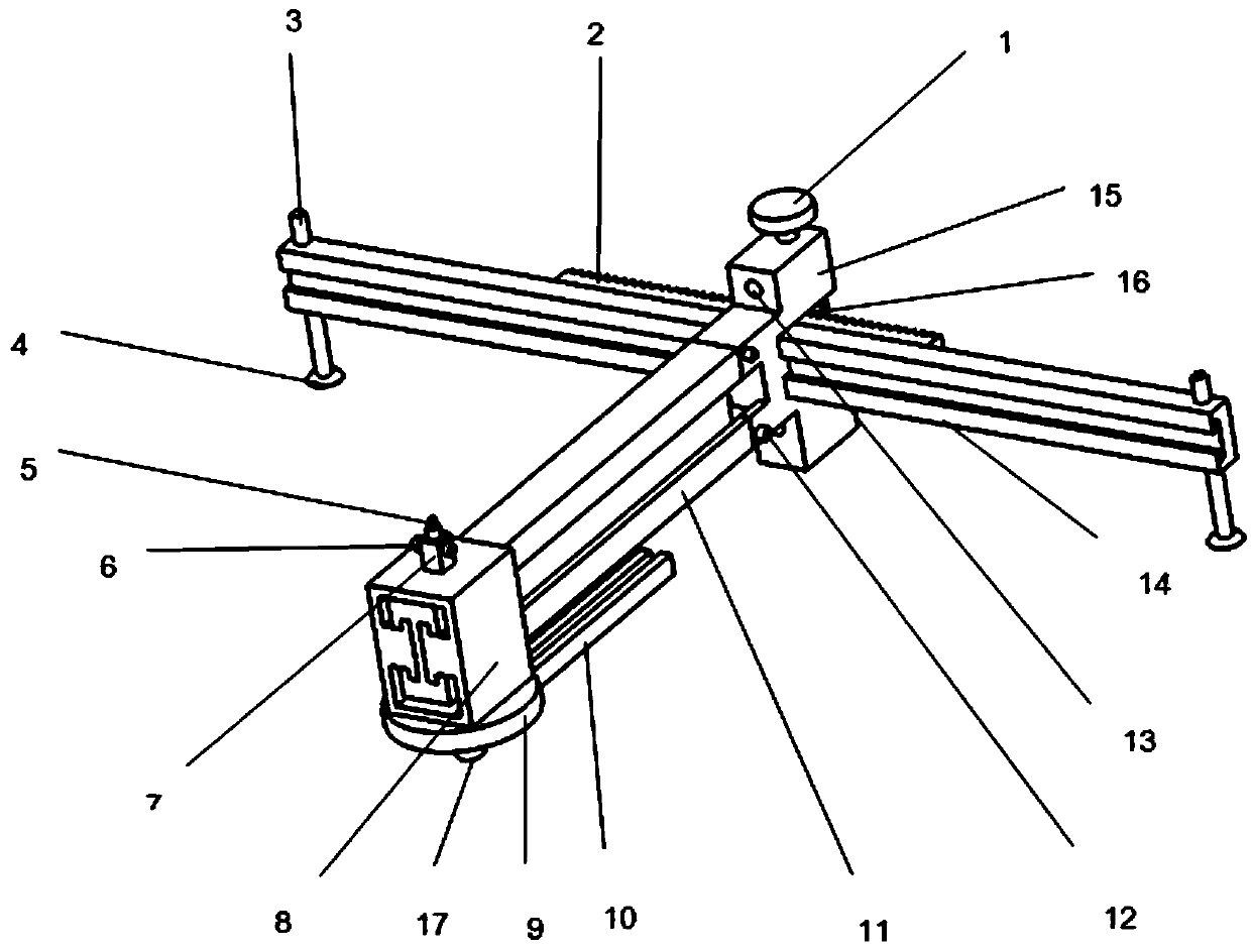
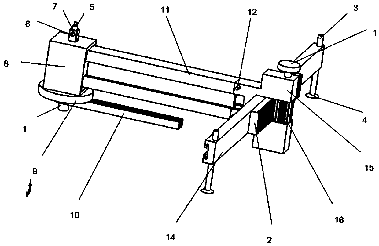
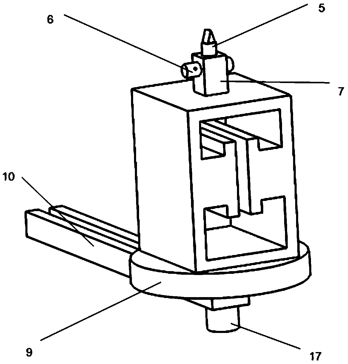
[0032] Such as Figure 1-4 As shown, a multifunctional glass cutting device includes a vertical guide rail 11, a transverse guide rail 14, a knife holder 8, an angle plate 9 and a cutter head.

[0033] Wherein, the vertical guide rail 11 is sleeved on the horizontal guide rail 14, the angle between the vertical guide rail 11 and the horizontal guide rail 14 in the horizontal direction is a right angle, the vertical guide rail 11 can move horizontally along the axial direction of the horizontal guide rail 14, and the knife rest 8 is sleeved On the vertical guide rail 11, the angle disc 9 is installed on the top or bottom of the knife rest 8, and the angle disc 9 is rotated to be provided with a rotating rod 10. When performing linear cutting, the cutter head is installed on the knife rest...


PUM


Abstract

The invention provides a multifunctional glass cutting device. A vertical guiderail is installed on a horizontal guiderail in a sliding way, a knife rest is installed on the vertical guiderail in a sliding way, a tool bit and an angle scale are respectively installed at the top and the bottom of the knife rest; the tool bit is located at the bottom of the knife rest in the linear cutting, the cutting position is determined by moving the vertical guiderail, and the straight cutting is implemented by moving the knife rest; the knife rest is installed on the vertical guiderail by rotating by 180degrees in the circular cutting or angular cutting, the angle scale is located at the bottom of the knife rest, the tool bit is installed on a rotating rod in a sliding way, the angle scale is taken as the center of a circle, the radius is determined according to the position of the tool bit in the rotating rod, the rotating rod is rotated to finish the circular cutting; the angle of the rotatingrod is also determined according to the angle scale, the tool bit slides along the rotating rod to cut to finish the angular cutting, the device integrates measuring and cutting, the cutting process of the glass is simplified, the working efficiency is improved, and the operation is simple.

Description

technical field [0001] The invention relates to the technical field of knife cutting, in particular to a multifunctional glass cutting device. Background technique [0002] Glass is something that can be seen everywhere in people's daily life. It has many shapes, and most of the cutting tools for glass are the same in the market. At the same time, it mainly depends on the craftsman's operation means and experience to cut different shapes, like a scale, Glass knives and the like are all indispensable, and sometimes a cutting machine is used. The above-mentioned cutting process is complicated, resulting in low work efficiency and large cutting errors. [0003] At present, the known glass knives are all composed of a knife head and a knife body at the tip of a glass knife, but most non-professionals cannot cut materials in various shapes by themselves due to the technical and experience involved in operation, such as circular, Special shapes such as curved surfaces can only be...

Claims


Application Information

Patent Timeline
IPC IPC(8): C03B33/027C03B33/04C03B33/10
CPCC03B33/027C03B33/04C03B33/105Y02P40/57
Inventor 栾飞马家豪金加庚桓源郑康乾刘柯
Owner SHAANXI UNIV OF SCI & TECH
Learn More