Self-adaptive structure for displacement of tunnel by active fault sectional mining method and installation method

A technology of active faults and mining methods, applied in tunnels, tunnel linings, mining equipment, etc., can solve problems such as voids, voids, and limited buffer range between the side of the tunnel and the filling layer, so as to reduce the amount of structural displacement and ensure elasticity. Restoring and avoiding the effect of dislocation of the tunnel structure

Pending Publication Date: 2019-04-26
CHINA RAILWAY SIYUAN SURVEY & DESIGN GRP
View PDF13 Cites 6 Cited by
  • Summary
  • Abstract
  • Description
  • Claims
  • Application Information

AI Technical Summary

Problems solved by technology

This technology has the following problems: 1) Before the filling material is installed (or poured), the deformation of the primary support of the tunnel has been stabilized, so the filling material and the secondary lining generally do not bear the pressure of the surrounding rock, but only bear the effect of self-weight and internal operating load. The compression deformation of the filling material itself is very small or even negligible, and the buffer range is very limited; 2) Although the elastic modulus of the filling material is much lower than that of the lining concrete, it is still a "rigid" material and has not been "pre-compressed". Therefore, when the fault moves up and down relative to each other, it will inevitably lead to the gap between the bottom of the tunnel on the "sinking" side and the filling layer, so that the tunnel lining will bear a large shear force and cause fracture.
Similarly, when the fault is displaced relative to the left and right, it will inevitably cause the side of the tunnel on one side to be separated from the filling layer, and the tunnel structure may also be broken due to excessive shear force.

Method used


Image

  • Self-adaptive structure for displacement of tunnel by active fault sectional mining method and installation method
  • Self-adaptive structure for displacement of tunnel by active fault sectional mining method and installation method
  • Self-adaptive structure for displacement of tunnel by active fault sectional mining method and installation method

Examples


Embodiment Construction

[0036] In order to make the object, technical solution and advantages of the present invention clearer, the present invention will be further described in detail below in conjunction with the accompanying drawings and embodiments. It should be understood that the specific embodiments described here are only used to explain the present invention, not to limit the present invention. In addition, the technical features involved in the various embodiments of the present invention described below can be combined with each other as long as they do not constitute a conflict with each other.

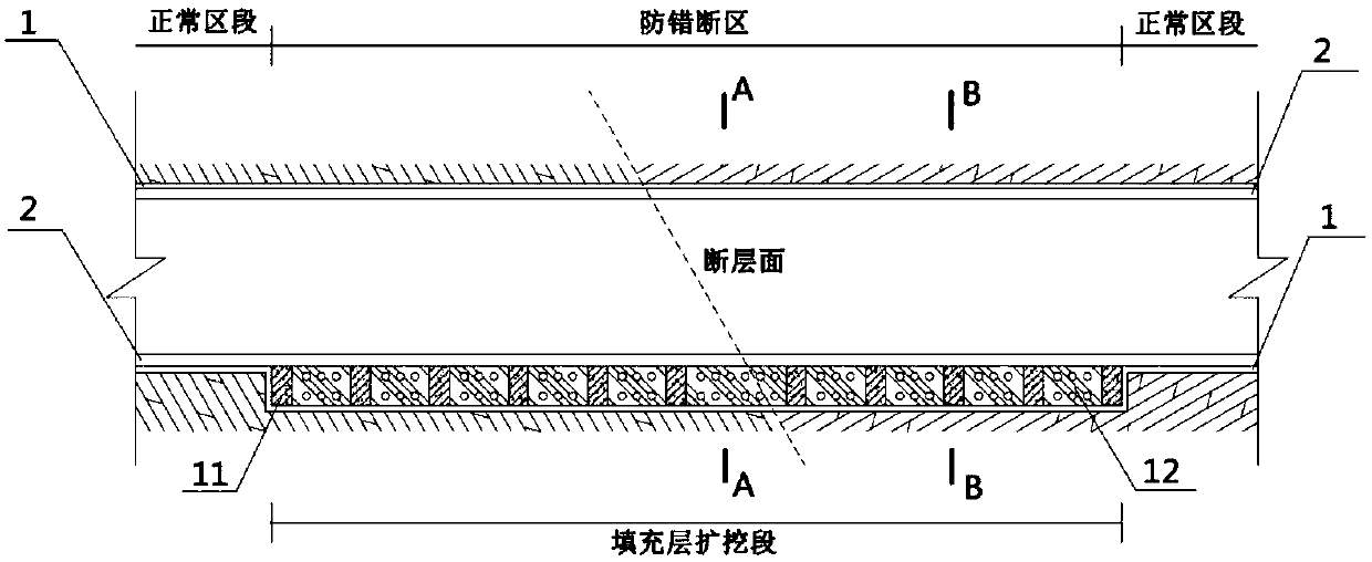
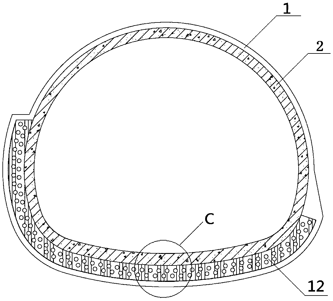
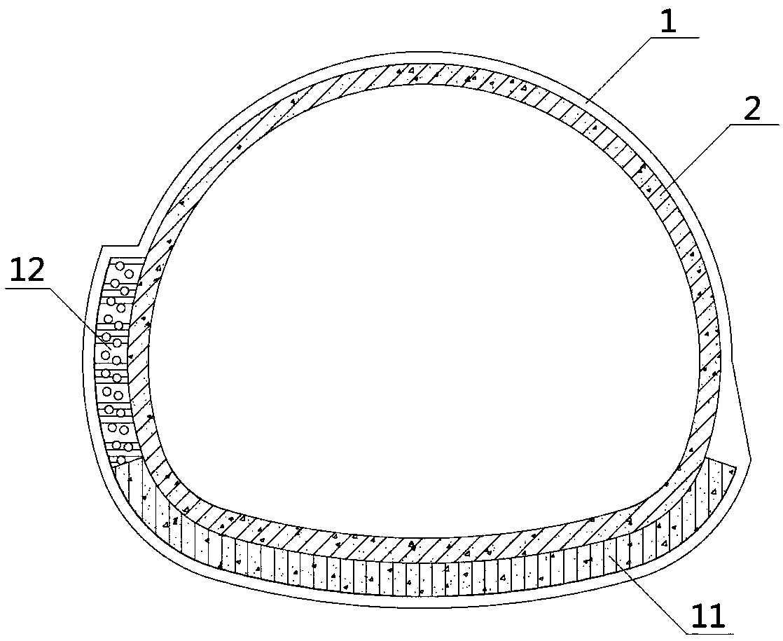
[0037] figure 1 It is a schematic diagram of a longitudinal section of a displacement adaptive structure of a mining tunnel in an active fault section according to an embodiment of the present invention. Such as figure 1 as shown, figure 2 for figure 1 Schematic diagram of the cross-sectional structure in A-A. image 3 for figure 1 Schematic diagram of the B-B cross-sectional structure. ...


PUM


Abstract

The invention discloses a self-adaptive structure for displacement of a tunnel by an active fault sectional mining method. An anti-offset area is arranged at a section, longitudinally crossing the active fault, of the tunnel, and comprises sprayed concrete (1), secondary lining (2) and a filling layer, wherein the filling layer is arranged between the sprayed concrete (1) and the secondary lining(2) and is of a half-coating structure; the filling layer comprises a bottom filling section and side filling sections, the bottom filling section is arranged at the bottom part of the tunnel, and theside filling sections are arranged at the side edges of the tunnel; porous rubber (12) is filled into each side filling section, a plurality of support piers (11) are arranged in the bottom filling section at intervals, the porous rubber (12) is arranged between the adjacent support piers (11), and the porous rubber (12) is of a pre-compressed structure. The invention also discloses an installation method of the self-adaptive structure for displacement of the tunnel by the active fault sectional mining method. The displacement self-adaptive structure provides by the invention provides supportfor the tunnel structure, and is capable of reducing the offsetting quantity of the structure.

Description

technical field [0001] The invention belongs to the technical field of mining tunnels, and more specifically relates to a displacement adaptive structure and installation method of mining tunnels in active fault sections. Background technique [0002] For tunnels built by the mining method, the tunnel structure generally adopts composite lining. The composite lining is mainly composed of primary support and secondary lining. After the surrounding rock is excavated, the primary support is formed by applying shotcrete, anchor rods and steel frames. After the deformation of the surrounding rock and the primary support structure is stable, pouring Concrete or reinforced concrete forms the secondary lining. [0003] When the mining method tunnel is located in a weak fractured zone, especially an active fault, the geological conditions of the surrounding rock are quite different. In the area of ​​active faults, the tunnel structure of the upper and lower walls of the strata has ...

Claims


Application Information

Patent Timeline
Patent Type & Authority Applications(China)
IPC IPC(8): E21D11/00E21D11/10G06F17/50
CPCE21D11/00E21D11/10G06F30/13G06F2119/06
Inventor 肖明清王少锋邓朝辉龚彦峰周坤徐晨
Owner CHINA RAILWAY SIYUAN SURVEY & DESIGN GRP
Why Eureka
Try Eureka