
Combined sliding surface spiral groove bearing

A spiral groove and sliding technology, which is applied in sliding contact bearings, rotating bearings, bearings, etc., can solve the problems of increased friction power consumption of oil film, large lubricating oil resistance, and difficult control of temperature rise, so as to reduce friction work consumption, increase oil film pressure and end discharge, and reduce frictional resistance

Pending Publication Date: 2019-04-26
SHANDONG UNIV OF SCI & TECH
View PDF0 Cites 0 Cited by
  • Summary
  • Abstract
  • Description
  • Claims
  • Application Information

AI Technical Summary

Problems solved by technology

[0004] Aiming at the deficiencies of the above-mentioned prior art, the object of the present invention is to propose a combined sliding surface spiral groove bearing, which solves the problem that the lubricating oil has too much resistance between the bearing pad and the rotating shaft, which leads to a significant increase in friction power consumption in the oil film, resulting in a load-bearing loss of the bearing. Force difference, the problem that the temperature rise of the bearing is difficult to control during high-speed operation

Method used


Image

  • Combined sliding surface spiral groove bearing
  • Combined sliding surface spiral groove bearing

Examples


Embodiment Construction

[0017] The present invention is described in detail below in conjunction with accompanying drawing:

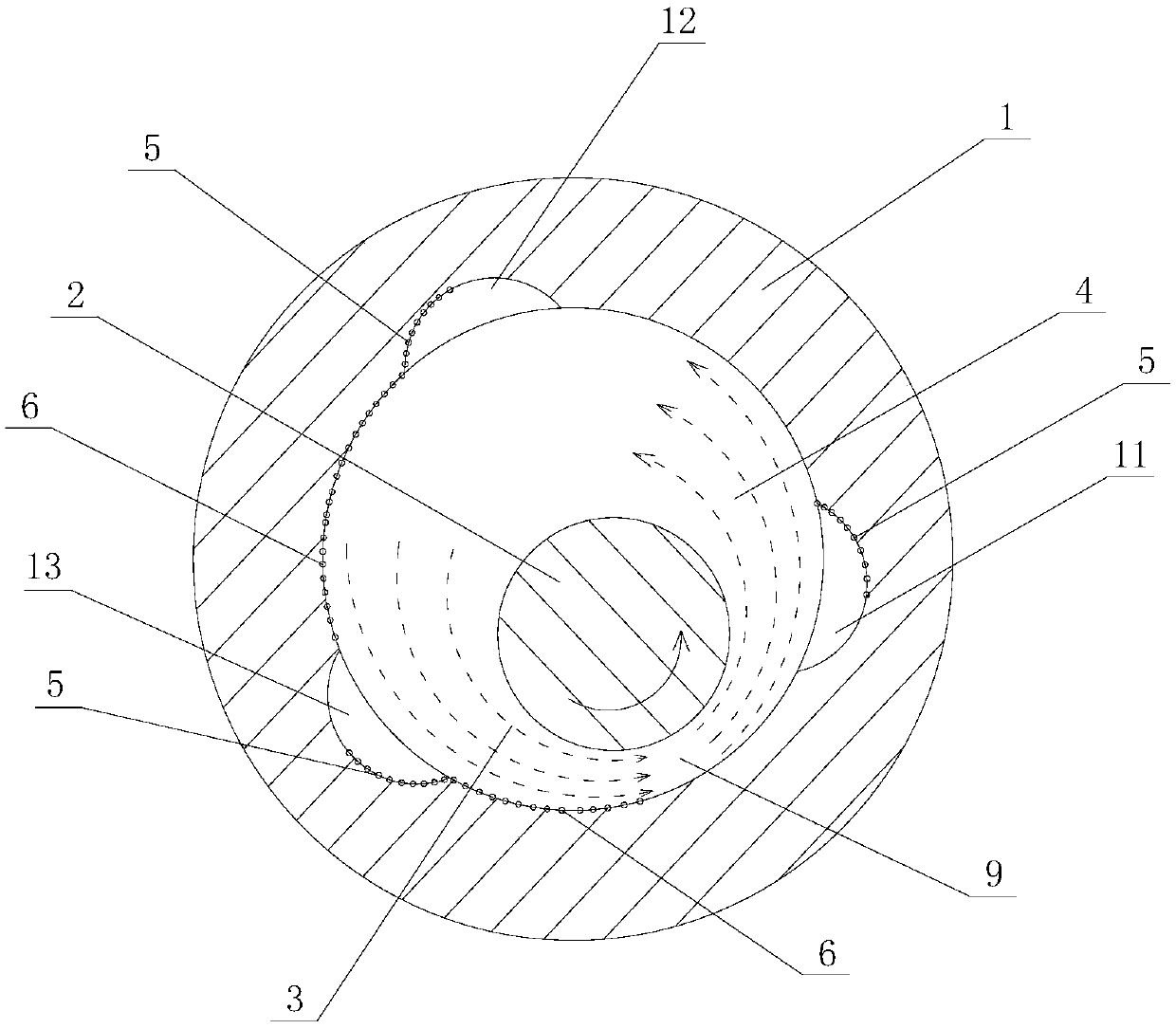
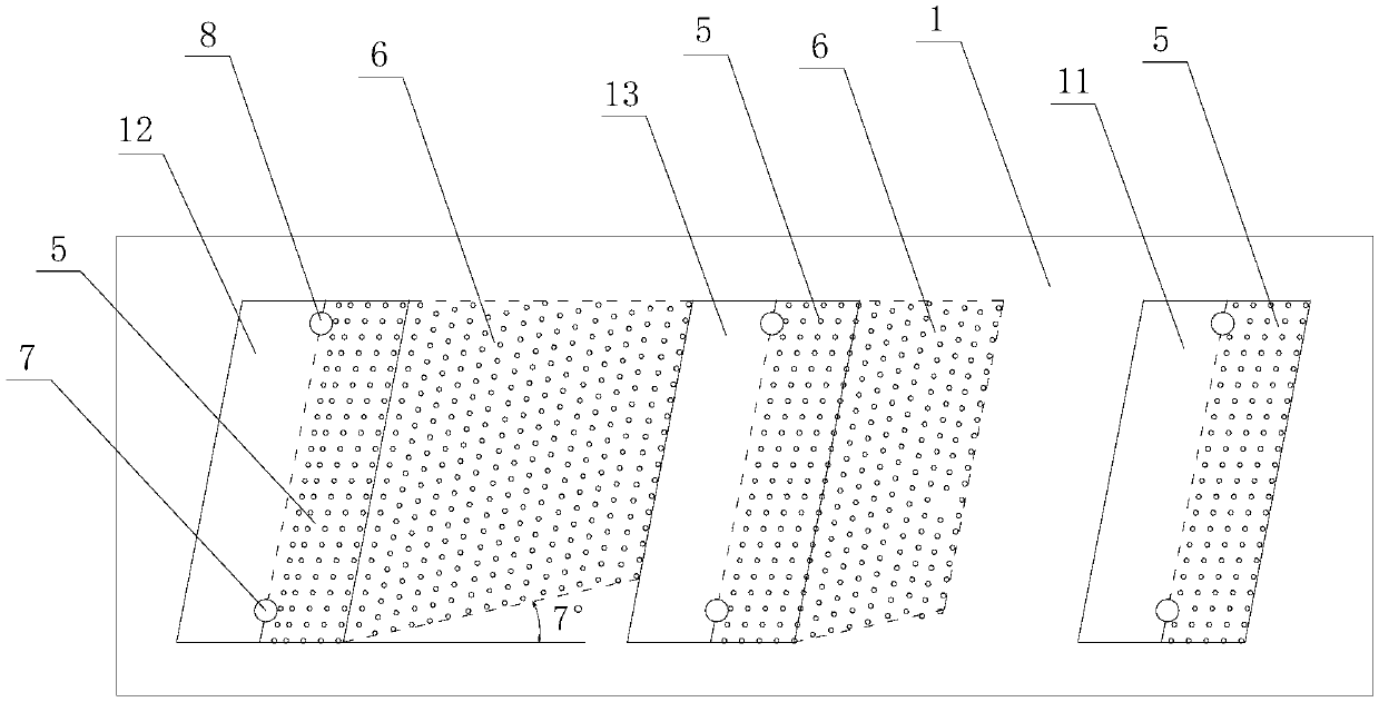
[0018] combine figure 1 with figure 2 , a combined sliding surface spiral groove bearing, including a bearing bush 1 and a rotating shaft 2, the rotating shaft 2 is arranged in the bearing bush 1, the bearing bush 1 is fixedly installed on the bearing seat, the rotating shaft 2 and the bearing bush 1 are in clearance fit, and the bearing bush 1 can be A split bearing or an integral bearing is adopted, and the present invention preferably adopts an integral bearing. In use state, the rotating shaft 2 rotates at a high speed inside the bearing bush 1, and the gap between the rotating shaft 2 and the bearing bush 1 is filled with lubricating oil, and the lubricating oil forms an oil film in a moving state. The axis of the high-speed rotating shaft 2 is located on the side of the shaft center of the bearing bush 1, and the gap between the bearing bush 1 and the rotating shaft 2...


PUM


Abstract

The invention discloses a combined sliding surface spiral groove bearing. A bearing bush and a rotation shaft are included. The rotation shaft is arranged in the bearing bush and is in clearance fit with the bearing bush. In the usage state, the axis of the rotation shaft is located below one side of the axis of the bearing bush, and an oil convergence area and an oil divergence area are formed bythe gap between the bearing bush and the rotation shaft in the rotation direction of the rotation shaft. A plurality of oil cavities are sequentially formed in the inner wall of the bearing bush at intervals in the circumference direction. Each oil cavity is internally provided with an oil inlet and an oil outlet. Sliding coating areas are arranged in all the oil cavities, the sliding coating areas located in the oil cavities in the convergence area extend in the rotation direction of the rotation shaft, and a sliding coating extension area is formed in the inner wall of the bearing bush. Coatings of the sliding coating areas and the sliding coating extension area are fluorocarbon coatings. The sliding character of the fluorocarbon coatings is utilized in the combined sliding surface spiral groove bearing, friction resistance is reduced, oil film inner friction power consumption is reduced, the oil film pressure and the end release amount are increased, heat is rapidly brought away, temperature rise of the bearing in the high-speed rotation process is restrained, and the bearing force for high-speed bearing rotation is improved.

Description

technical field [0001] The invention relates to the technical field of bearings, in particular to a combined sliding surface spiral groove bearing. Background technique [0002] High-speed and ultra-high-speed cutting have gradually become the mainstream of cutting technology and machine tool development. As an important support method, bearings have become an important factor affecting the speed and stability of machine tools. Hydrodynamic and static pressure bearings have high bearing capacity, high stiffness and high rotation accuracy, and have great application potential in high-speed rotating machinery. Heat generation is the fundamental reason that restricts the speed increase of dynamic and static pressure bearings. When the speed increases, the internal friction power consumption of the oil film increases significantly, resulting in an increase in the temperature rise of the oil film, and even a "shaft holding" accident in severe cases. The problem of temperature ri...

Claims


Application Information

Patent Timeline
IPC IPC(8): F16C17/24F16C33/16F16C37/00
CPCF16C17/243F16C33/16F16C37/00F16C2300/22F16C2202/50
Inventor 王丽丽孙静
Owner SHANDONG UNIV OF SCI & TECH
Learn More