
Light module

A technology of optical modules and optical fibers, which is applied in the field of optical communications, can solve problems such as inability to accommodate components, difficult assembly, poor heat dissipation of light emitting modules, etc., and achieve the effects of improving transmission speed, realizing layout, and high-density layout

Pending Publication Date: 2019-04-26
INNOLIGHT TECHNOLOGY (SUZHOU) LTD
View PDF4 Cites 5 Cited by
  • Summary
  • Abstract
  • Description
  • Claims
  • Application Information

AI Technical Summary

Problems solved by technology

The number of lasers, chips, and optical components that can be accommodated in this light emitting module is limited by the sub-optical components and arrangement, and cannot accommodate more components
In addition, this kind of light emission module has poor heat dissipation and is difficult to assemble.

Method used


Image

  • Light module
  • Light module
  • Light module

Examples


Embodiment Construction

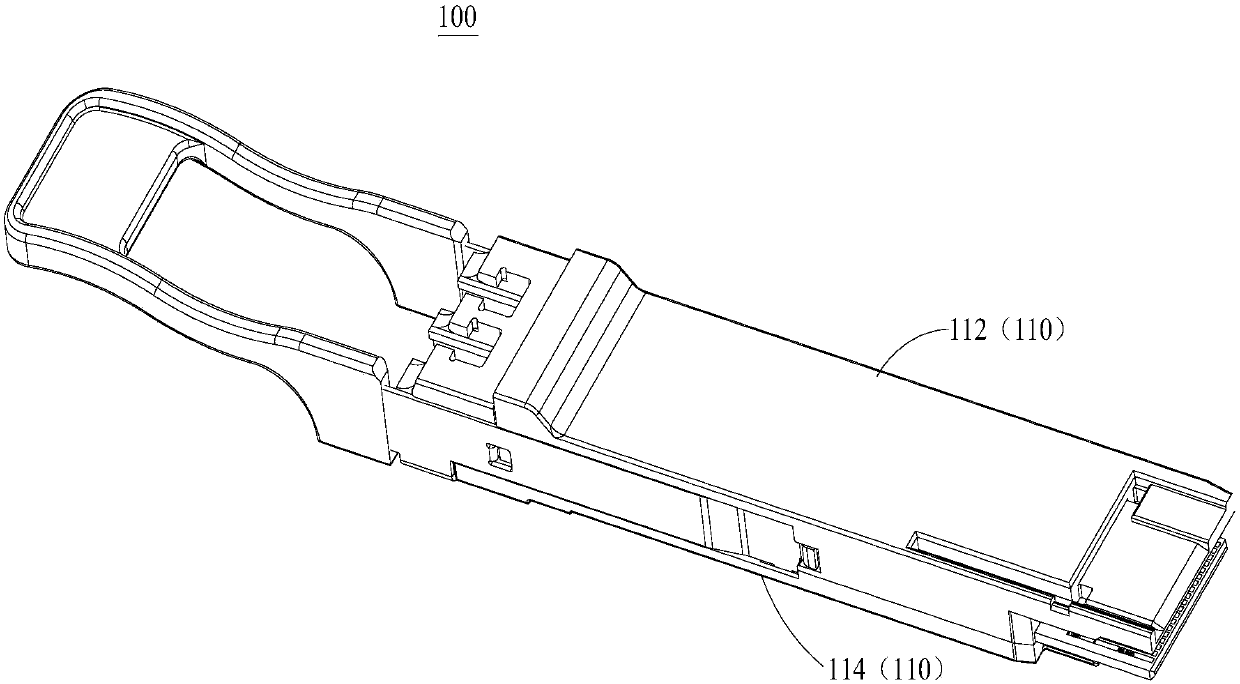
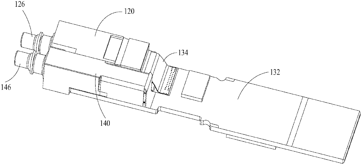
[0022] The application will be described in detail below in conjunction with specific implementations shown in the accompanying drawings. However, these implementations do not limit the present application, and any structural, method, or functional changes made by those skilled in the art based on these implementations are included in the protection scope of the present application.

[0023] In each drawing of the present application, some dimensions of structures or parts are exaggerated relative to other structures or parts for convenience of illustration, and therefore, are only used to illustrate the basic structure of the subject matter of the present application.

[0024] In addition, terms used herein such as "upper", "above", "under", "below", etc. to express relative positions in space are for convenience of description to describe a unit or feature as shown in the drawings relative to A relationship to another cell or feature. The terms of spatial relative position ...


PUM


Abstract

The invention discloses a light module. A light emitting assembly and a light receiving assembly of the light module are separately provided with two or more photoelectric chips and then assembled, inthis way, more elements are arranged in a limited space, then high-density layout is realized, and convenience is provided for increase of transmission speed of the light module.

Description

technical field [0001] The invention relates to the field of optical communication, in particular to an optical module. Background technique [0002] With the rapid development of optical communication and the Internet in recent years, users' demand for the network has also increased rapidly, which has led to a rapid increase in the traffic of the telecommunications backbone network at a rate of 50% to 80% every year. In order to adapt to the rapid development trend of the network market, the transmission speed of optical modules is also increasing rapidly, and now 100G, 200G and even 400G optical modules have appeared. The increase in the speed of the optical module will cause great problems, such as heat dissipation and miniaturization. It has become a great challenge in the industry to arrange more optical components in a smaller optical module housing while taking heat dissipation into consideration. [0003] Chinese patent CN201420189088.1 discloses a replaceable ligh...

Claims


Application Information

Patent Timeline
Patent Type & Authority Applications(China)
IPC IPC(8): G02B6/42
CPCG02B6/4246G02B6/4272H04B10/40G02B6/428G02B6/4284G02B6/4204G02B6/426G02B6/4281
Inventor 陈龙孙雨舟翟雄飞王冬寒汪振中方萌张超方习贵王祥忠
Owner INNOLIGHT TECHNOLOGY (SUZHOU) LTD
Learn More